Transmission structure of hollow cup tubular motor

A technology of tubular motor and transmission structure, which is applied in the direction of transmission, electric components, gear transmission, etc. It can solve the problems that the reduction ratio of the reducer cannot meet the demand, the output torque of the motor is limited, and the transmission stability is poor, so as to achieve the braking effect Good, the effect of improving the response speed and increasing the output torque

Pending Publication Date: 2019-09-20
HANGZHOU WISTAR MECHANICAL& ELECTRIC TECH CO LTD
View PDF1 Cites 1 Cited by
  • Summary
  • Abstract
  • Description
  • Claims
  • Application Information

AI Technical Summary

Problems solved by technology

There are many deficiencies in the existing tubular rare earth or ferrite motors, for example: 1. There is a rotor iron core, and the mass of the rotor iron core is large, so that the rotor has slow response speed, high energy consumption, and large vibration when starting and stopping. The damage to the components is serious, which limits the life of the whole machine; secondly, the rotor core will generate eddy currents in the magnetic field, which will cause the motor to heat up, consume high energy, and have low efficiency
2. The magnetic tile (permanent magnet) is fixed on the casing, and the magnetic tile (permanent magnet) must have a certain thickness. In the case of a certain external diameter of the motor, the external diameter of the motor rotor will be greatly restricted, thus The output torque of the motor is greatly limited
The above solution solves the problem that the reduction ratio of the reducer of the existing tubular motor cannot meet the demand to a certain extent, but this solution still has many shortcomings of ordinary rare earth or ferrite motors, and at the same time, this solution still has other shortcomings. For example, poor transmission stability, etc.

Method used


Image

  • Transmission structure of hollow cup tubular motor
  • Transmission structure of hollow cup tubular motor
  • Transmission structure of hollow cup tubular motor

Examples


Embodiment Construction

[0031] The present invention will be described in further detail below in conjunction with the accompanying drawings and specific embodiments.

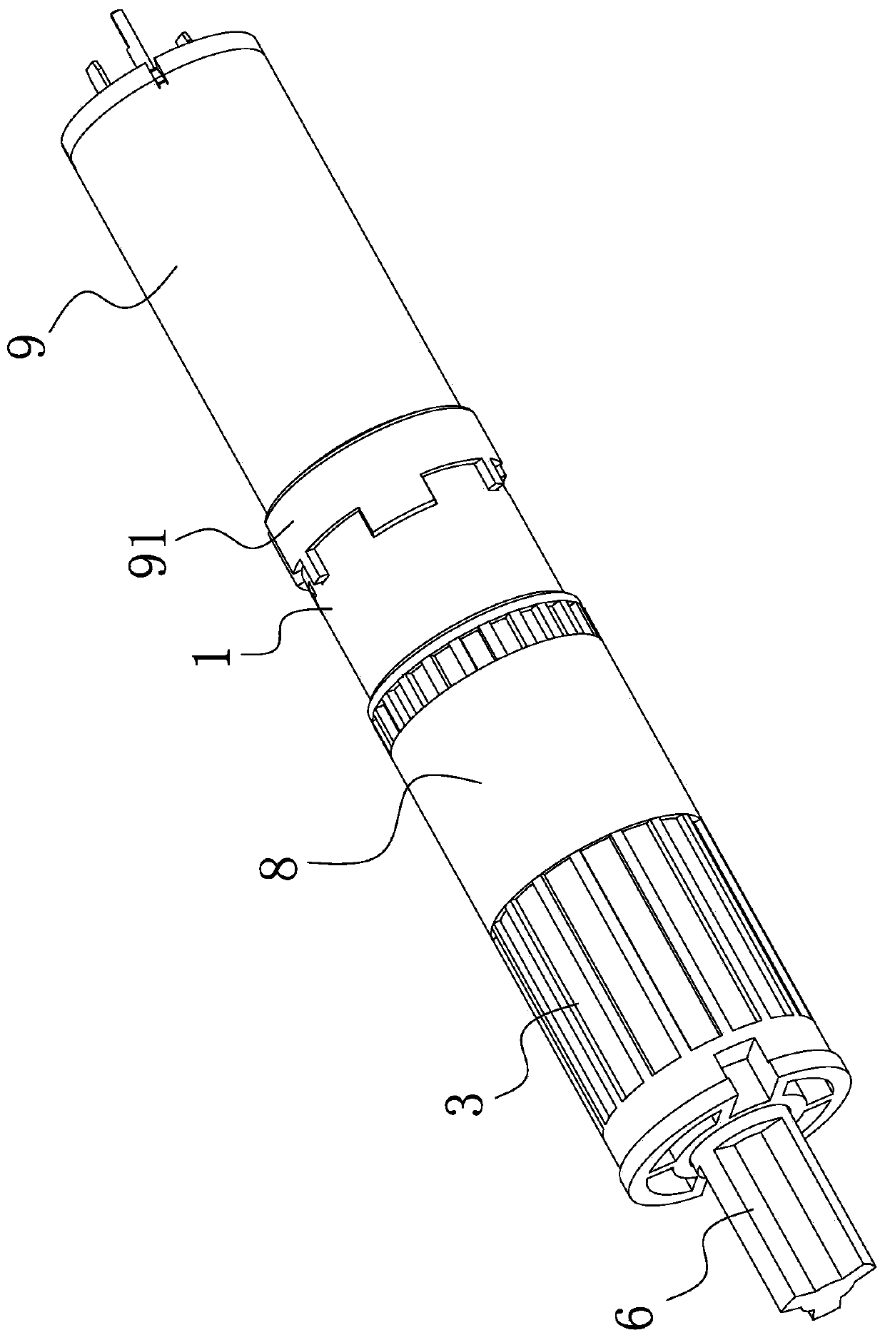
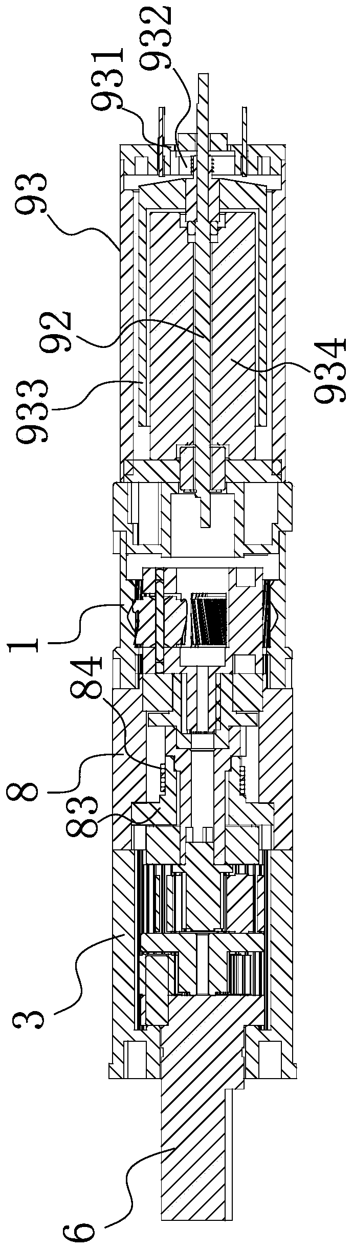
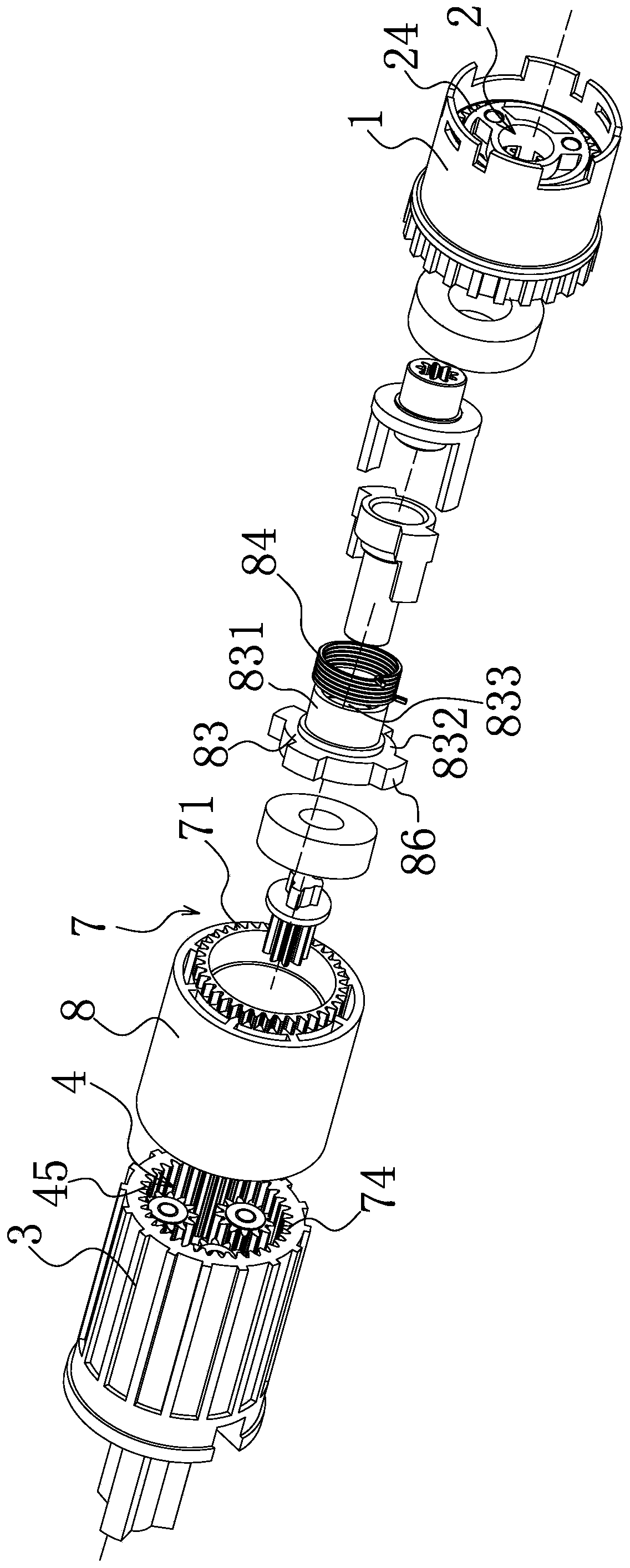
[0032] Such as figure 1 and 3 As shown in -9, the transmission structure of the coreless tubular motor includes a motor body 9, the motor body 9 is connected to one end of the first-stage ring gear 1 through a motor connecting seat 91, and the motor shaft 92 of the motor body 9 is arranged on the first-stage gear The first-stage planetary gear assembly 2 in the ring 1 is connected, and the other end of the first-stage ring gear 1 is connected to the second-stage and third-stage ring gear 3 with the second-stage planetary gear assembly 4 and the third-stage planetary gear assembly 5 through the brake casing 8, and the third-stage planetary gear assembly 5 The input end of the gear assembly 5 is connected to the output end of the second-stage planetary gear assembly 4, the output end of the third-stage planetary gear assembly 5 is conn...


PUM


Abstract

The invention relates to a transmission structure of a hollow cup tubular motor, and solves the problem that an existing transmission structure of the tubular motor is insufficiently reasonable in design. The transmission structure comprises a motor main body, a motor connecting seat, a primary gear ring, a primary planetary gear assembly, a brake outer sleeve, a secondary planetary gear assembly, a ternary planetary gear assembly and a secondary and ternary gear ring, wherein the motor main body is a hollow cup motor; a brake driving part and a brake driven part which are coaxially arranged are arranged in the brake outer sleeve in a penetrating mode; the brake driving part is connected with the output end of the primary planetary gear assembly; the brake driven part is connected with the input end of the secondary planetary gear assembly; the brake driving part is in transmission connection with the brake driven part; and a brake assembly connected with the brake driving part and the brake driven part is arranged on the inner side of the periphery of the brake outer sleeve. The transmission structure has the advantages that the transmission stability is high, the component layout is reasonable, the structure is compact, and the brake effect is good.

Description

technical field [0001] The invention belongs to the technical field of motor equipment, and in particular relates to a transmission structure of a hollow cup tubular motor. Background technique [0002] With the rapid development of the electromechanical industry, motors have been widely used in our current lives. For example, tubular motors have the advantages of compact structure, large torque, and slow speed as driving devices. Therefore, tubular motors are increasingly used in Rolling shutter doors and windows, sunshade systems, projection screens and other products that complete the lifting movement electrically. Since the motor shaft of the tubular motor rotates too fast, a reducer is generally provided on the tubular motor for ease of use, so that the rotational speed of the output shaft meets the needs of normal use. Existing DC tubular motors are generally ordinary rare earth or ferrite motors, which have structural features such as rotor iron cores and magnetic ti...

Claims


Application Information

Patent Timeline
Patent Type & Authority Applications(China)
IPC IPC(8): H02K7/116H02K7/102
CPCH02K7/116H02K7/102H02K2207/03H02K23/04H02K23/58H02K7/14F16H1/46F16H57/10F16D49/04F16D2127/005F16D59/00F16H35/00F16H2035/005H02K21/14
Inventor 孙旭东朱才龙
Owner HANGZHOU WISTAR MECHANICAL& ELECTRIC TECH CO LTD
Why Eureka
Try Eureka