

Hub type blade and manufacturing method of hub type blade
A manufacturing method and hub-type technology, which is applied in manufacturing tools, semiconductor/solid-state device manufacturing, bonded grinding wheels, etc., can solve the problems of expansion difference between the aluminum base metal and the blade body, long time, and cost, and achieve resource saving and reduction Manufacturing cost, effect of suppressing deformation or warpage
- Summary
- Abstract
- Description
- Claims
- Application Information
AI Technical Summary
Problems solved by technology
Method used
Image

Examples
no. 1 approach
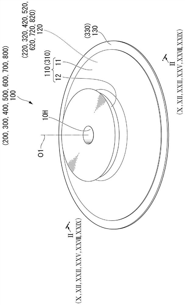
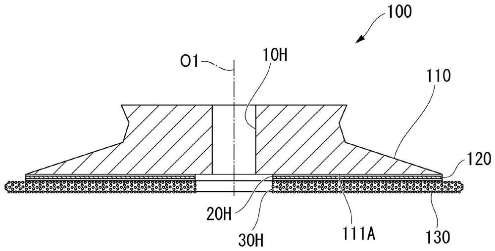
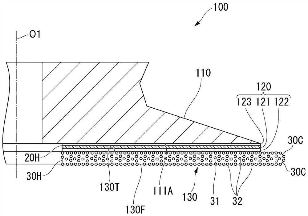
[0149] Below, refer to Figure 1 ~ Figure 3 , the hub blade according to the first embodiment of the present invention will be described.
[0150] figure 1 It is a perspective view explaining an example of the schematic structure of the hub type insert concerning 1st Embodiment of this invention, figure 2 is in figure 1 In the cross-sectional view indicated by arrow II-II, image 3 is an enlarged partial cross-sectional view.
[0151] exist Figure 1 ~ Figure 3 Among them, reference numeral 100 denotes a hub-type blade, reference numeral 110 denotes a hub, reference numeral 120 denotes a double-sided adhesive tape, and reference numeral 130 denotes a blade body.
[0152] Such as figure 1 As shown, the hub blade 100 includes, for example, a hub 110, a double-sided adhesive tape 120, and a blade body 130, and is capable of dicing a wafer (substrate such as a semiconductor material) and singulating it into IC chips (chip shape).
[0153] Such as Figure 1 ~ Figure 3 A...
no. 2 approach
[0273] Below, refer to Figure 10 and Figure 11 , the hub blade according to the second embodiment of the present invention will be described.
[0274] Figure 10 It is a perspective view illustrating an example of a schematic structure of a hub blade according to a second embodiment of the present invention, and is in figure 1 The cross-sectional view indicated by the arrow X-X. in addition, Figure 11 is in Figure 10 Enlarged view of the portion indicated by XI in .
[0275] exist Figure 10 and Figure 11 In , reference numeral 200 denotes a hub-type blade, reference numeral 110 denotes a hub, reference numeral 220 denotes a double-sided adhesive tape, and reference numeral 130 denotes a blade body.
[0276] Such as Figure 10 As shown, the hub blade 200 includes, for example, a hub 110 , a double-sided adhesive tape (adhesive connection portion) 220 , and a blade body 130 .
[0277] Since the hub 110 and the blade main body 130 are the same as those in the fir...
no. 3 approach
[0295] Below, refer to figure 1 , Figure 12 ~ Figure 13 , the hub blade according to the third embodiment of the present invention will be described.
[0296] Figure 12 yes figure 1 The cross-sectional view indicated by the arrow XII-XII in the middle, Figure 13 is an enlarged partial cross-sectional view.
[0297] In the drawings, reference numeral 300 denotes a hub-type blade, reference numeral 310 denotes a hub, reference numeral 320 denotes an adhesive resin portion (adhesive, connecting portion), and reference numeral 330 denotes a blade main body.
[0298] Such as figure 1 , Figure 12 and Figure 13 As shown, the hub blade 300 includes, for example, a hub 310, an adhesive resin portion (adhesive joint, connecting portion) 320, and a blade body 330, and is capable of dicing a wafer (substrate such as a semiconductor material) and singulating it into IC chips or the like.
[0299] Such as figure 1 , Figure 12 and Figure 13 As shown, the hub 310 include...
PUM
| Property | Measurement | Unit |
|---|---|---|
| surface roughness | aaaaa | aaaaa |
| thickness | aaaaa | aaaaa |
| particle diameter | aaaaa | aaaaa |
Abstract
Description
Claims
Application Information