Double rotary knife roll paper splitting machine

A roll paper, double-rotating technology, applied in metal processing, winding strips, sending objects, etc., can solve the problems of low production efficiency of paper cutters, affecting paper cutting and processing efficiency, and many sawtooth and burrs

Pending Publication Date: 2019-09-24
DONGGUAN JUNXING MACHINERY TECH
View PDF1 Cites 4 Cited by
  • Summary
  • Abstract
  • Description
  • Claims
  • Application Information

AI Technical Summary

Problems solved by technology

[0004] The deficiencies in the existing automatic equipment for cutting and processing paper are as follows: first, the existing paper cutting equipment uses the paper feeding device to directly feed the roll paper to the slitting assembly and the cross-cutting assembly. The roll paper is used for direct feeding. When the roll paper reaches the slitting assembly and the cross-cutting assembly, the roll paper will be warped to a certain extent, which will cause large size errors, serrations and burrs on the slitting and cross-cutting paper. Paper jams are caused by warping, which affects the processing efficiency of paper cutting; secondly, the existing paper cutting equipment is not equipped with edge guides or deviation correction devices directly between the paper feeding device and the cutting device, and the roll paper will be damaged during the feeding process. Due to the long-term rolling conduction of the conductive roller, it will translate along its axial direction, which will cause the deviation of the web during drafting. If it is not corrected, the web will be cut obliquely during the slitting and cross-cutting process. Therefore, the cut paper does not conform to the prescribed shape and size, resulting in waste of paper; third, the existing paper cutting equipment is still sent to the cross-cutting knife group in a single sheet after the roll paper is slitting. Therefore, the utilization rate of cutting, paper feeding and paper stacking is low, and the production efficiency of the paper cutter is low

Method used


Image

  • Double rotary knife roll paper splitting machine
  • Double rotary knife roll paper splitting machine
  • Double rotary knife roll paper splitting machine

Examples


Embodiment Construction

[0039] The present invention will be described in further detail below in conjunction with the accompanying drawings.

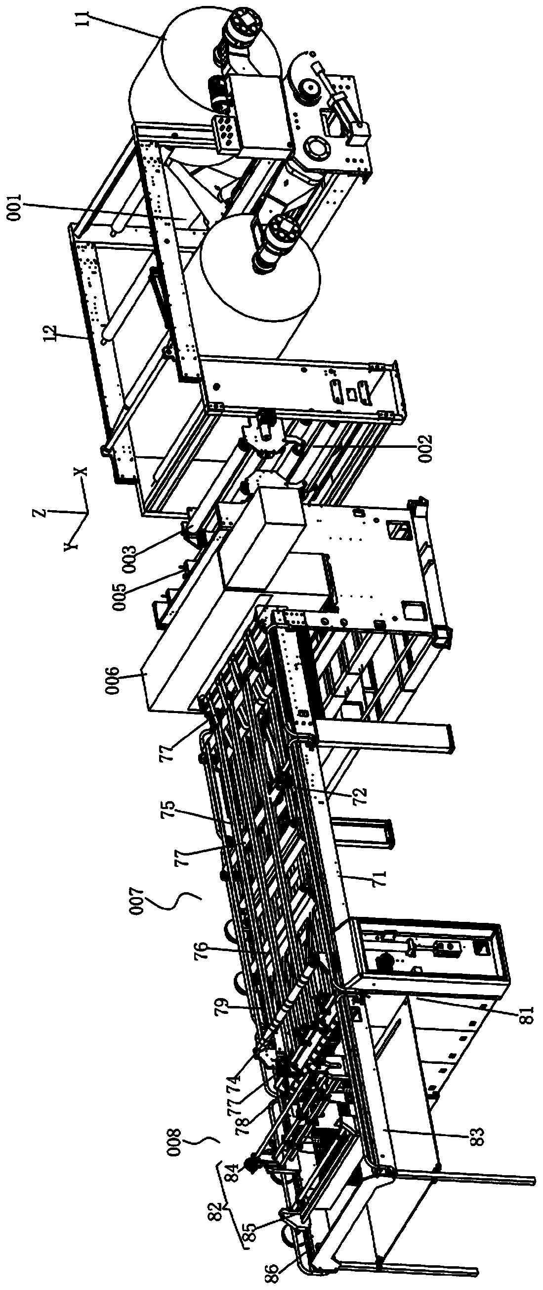
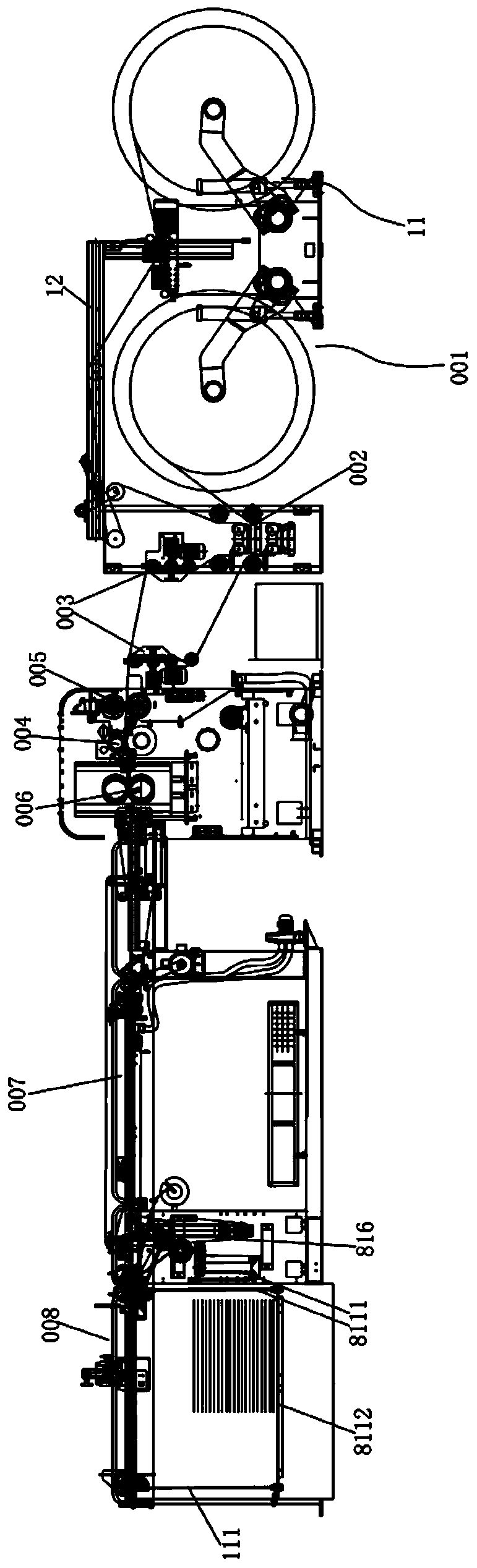
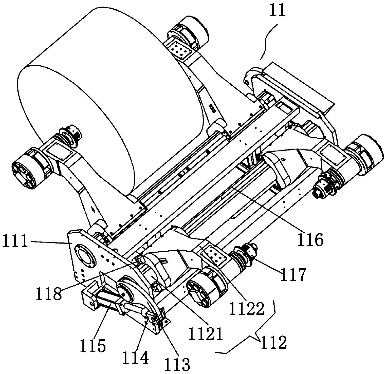
[0040] attached Figure 1-11 Embodiment A kind of embodiment of the present invention, refer to appended Figure 1-11 , a double rotary knife drum paper cutting machine, it includes:

[0041] The paper feeding system 001 includes multiple paper feeding devices 11, and the multiple paper feeding devices 11 cooperate with the deviation correction system 002 and the recurve system 003 arranged on the bridge frame 12 to stack multiple roll papers (the so-called stacking refers to one sheet on top of the other). placement, the number of sheets of roll paper matches the number of paper feeding device 1) and is transported along the transverse direction (X direction);

[0042] The traction system 004 is arranged between the slitting system 005 and the double rotary drum cross cutter 006, including the traction roller 43 and the traction pressure roller 44 installe...


PUM


Abstract

The invention discloses a double rotary knife roll paper splitting machine which comprises a paper supply system, a traction system, a conveying system and a paper collecting system. The paper supply system is used for being matched with a correcting system and a retroflection system to transfer a plurality of roller paper layers along a transverse direction; the traction system is used for sending laminated roll paper to a traction system of double rotary roller trimmer knife after pulling the roll paper to a stripping system; the conveying system comprises a high speed lower conveying assembly and a laminated paper conveying assembly in butt joint connection through a paper pass assembly and also comprises a high speed upper conveying assembly, a reducing assembly and a paper pressing assembly; the high speed lower conveying assembly and the laminated paper conveying assembly are matched with the high speed upper conveying assembly, and a pile of paper can be overlapped to the previous pile of paper successively and is transferred to the paper collecting system by matching with a conveying speed difference generated by the high speed upper conveying assembly and the laminated paper conveying assembly with reduction of the reducing assembly; and the paper collecting system is used for carrying each pile of paper and stacking the paper.

Description

technical field [0001] The invention relates to the technical field of paper cutting equipment, in particular to a double-rotating-knife roller paper cutting machine. Background technique [0002] The paper cutter is used to cut the required specifications of paper. From the traditional mechanical paper cutter to today's computer program control, the production preparation time is shorter, the cutting accuracy is higher, the labor intensity is lower, and the operation is safer. , and with the development of the market economy, more and more investors need a paper cutter with less space, less investment, quick return and strong operability. [0003] For large-volume paper processing and production, in order to improve production efficiency, modern production methods use assembly line for operation, and automatic machinery and equipment are equipped in each corresponding department of the assembly line, which greatly reduces the labor intensity of workers. [0004] The defici...

Claims


Application Information

Patent Timeline
Patent Type & Authority Applications(China)
IPC IPC(8): B65H20/02B65H35/02B65H35/08B65H16/06B65H23/038B65H23/26B65H23/188B65H23/34B65H31/38B65H31/28B26D7/32B26D1/15
CPCB26D1/15B26D7/32B26D2007/322B65H16/06B65H20/02B65H23/038B65H23/1888B65H23/26B65H23/34B65H31/28B65H31/38B65H35/02B65H35/08B65H2701/1133
Inventor 钟爵麟
Owner DONGGUAN JUNXING MACHINERY TECH
Why Eureka
Try Eureka