Automatic production line for heat-preservation decoration composite boards

An automatic production line and production line technology, applied in the direction of layered products, lamination devices, transportation and packaging, etc., can solve the problems affecting the quality of composite boards, high defective rate, the positioning effect and appearance quality of composite boards need to be improved, and achieve Compact device, health protection, and space-saving effects

Active Publication Date: 2019-09-24
XUZHOU COLLEGE OF INDAL TECH
6 Cites 10 Cited by

AI-Extracted Technical Summary

Problems solved by technology

[0004] However, the production process of thermal insulation and decorative composite panels and its production line provided in the above technical solutions st...

Abstract

The invention discloses an automatic production line for heat-preservation decoration composite boards and particularly relates to the field of building material processing. The automatic production line comprises a heat-preservation board production line, a veneer production line and a composite production line, a first conveying belt is arranged on the heat-preservation board production line, the veneer production line is provided with a second conveying belt, a third conveying belt is arranged on the composite production line, and a center conversion assembly is arranged at the junction of the first conveying belt and the second conveying belt. A camera and an ultrasonic sensor are matched with a single chip microcomputer for detection and analysis, the output end of a first air cylinder is controlled to extend out to remove veneer rejected products, glass fiber cotton fibers are sprayed on the surfaces of qualified boards, and thus the performance of the composite boards is improved; and the two kinds of boards are composited in a bonded mode, then conveyed to a shunting assembly and positioned on guiding boards, the positioning effect is good, then the boards are conveyed to the third conveying belt to be composited, the composite boards are clamped to be scraped by two clearing boards, the two layers of boards are aligned to remove excess binders, and the quality of the composite boards can be improved.

Application Domain

Technology Topic

Image

  • Automatic production line for heat-preservation decoration composite boards
  • Automatic production line for heat-preservation decoration composite boards
  • Automatic production line for heat-preservation decoration composite boards

Examples

  • Experimental program(1)

Example Embodiment

[0040] The technical solutions in the embodiments of the present invention will be clearly and completely described below with reference to the accompanying drawings in the embodiments of the present invention. Obviously, the described embodiments are only a part of the embodiments of the present invention, but not all of the embodiments. Based on the embodiments of the present invention, all other embodiments obtained by those of ordinary skill in the art without creative efforts shall fall within the protection scope of the present invention.
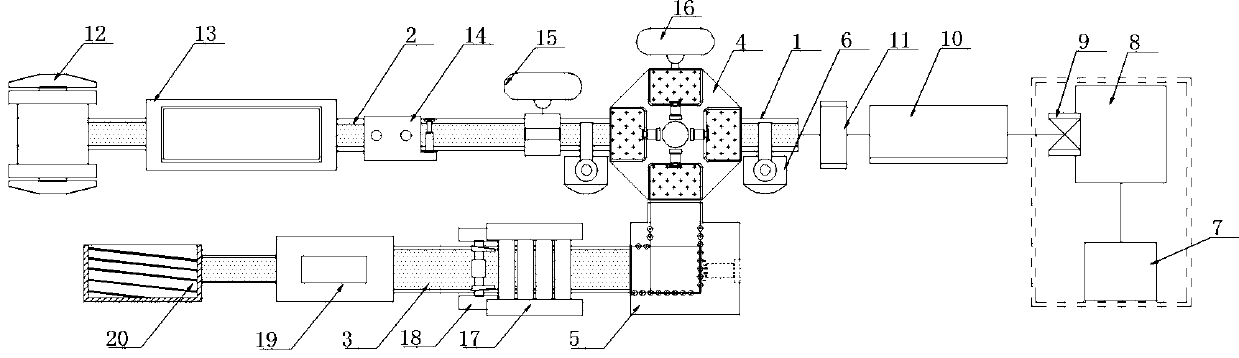
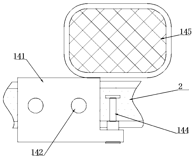
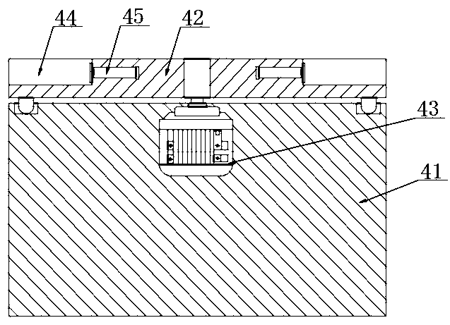
[0041] according to Figure 1-7 The shown automatic production line for thermal insulation and decorative composite panels includes a thermal insulation board production line, a decorative panel production line and a composite production line. The thermal insulation board production line is provided with a first conveyor belt 1, and the decorative panel production line is provided with a second conveyor belt 2. The composite production line is provided with a third conveyor belt 3 , the connection between the first conveyor belt 1 and the second conveyor belt 2 is provided with a central conversion assembly 4 , and the connection between the central conversion assembly 4 and the third conveyor belt 3 is provided with a rotary switch. Line assembly 5, both sides of the pivot conversion assembly 4 are provided with handling robots 6;
[0042] One end of the first conveyor belt 1 away from the central conversion assembly 4 is provided with a mixer 7, the output end of the mixer 7 is provided with a molding machine 8, and the output end of the molding machine 8 is provided with a cutting machine 9 , the output end of the cutting machine 9 is provided with a steam curing kettle 10, and the output end of the steam curing kettle 10 is provided with a dryer 11;
[0043] One end of the second conveyor belt 2 away from the central conversion assembly 4 is provided with an unwinder 12 , the output end of the unwinder 12 is provided with a forming machine 13 , and the output end of the forming machine 13 is provided with a detection component 14 . The output end of the detection component 14 is provided with a first unloading nozzle 15, and one side of the central conversion component 4 is provided with a second unloading nozzle 16;
[0044] One end of the third conveyor belt 3 close to the line transfer assembly 5 is provided with a roller press 17, the output end of the roller press 17 is provided with a cleaning assembly 18, and the output end of the cleaning assembly 18 is provided with a packaging machine 19, so The output end of the packaging machine 19 is provided with a receiving fence 20;
[0045] The detection assembly 14 includes a detection table 141 , a detection module 142 is provided on one side of the detection table 141 , a single-chip microcomputer 143 is provided at the connection end of the detection module 142 , and a first cylinder 144 is fixedly connected to the output end of the detection table 141 . , a storage basket 145 is arranged on one side of the single chip 143;
[0046] The pivot conversion assembly 4 includes a pivot base 41 , a top of the pivot base 41 is rotatably connected with a turntable 42 , and a drive motor 43 is fixedly connected inside the pivot base 41 , and the output shaft of the drive motor 43 is connected to the turntable 42 via transmission. , the outer side of the top of the turntable 42 is provided with a plate slot 44, and a second cylinder 45 is fixedly connected to the inside of the plate slot 44 close to the drive motor 43;
[0047] The wire turning assembly 5 includes a wire turning table 51 . The top of the turning table 51 is provided with a positioning groove 52 , the bottom of the positioning groove 52 is provided with a guide plate 53 , and two sides of the positioning groove 52 are provided with evenly distributed guides. A roller 54, a third cylinder 55 is fixedly connected to one side of the positioning groove 52;
[0048] The cleaning assembly 18 includes two cleaning plates 181. The cleaning plate 181 is provided with a wiping roller 182 inside, and the wiping roller 182 is made of cotton fiber material. The two cleaning plates 181 are symmetrically distributed in a figure-eight shape. The cleaning plates 181 are respectively fixedly connected on both sides of the output end of the roller press 17;
[0049] The first blanking nozzle 15 is used for spraying glass fiber cotton fibers on the decorative panel, and the second blanking nozzle 16 is used for spraying adhesive on the decorative panel;
[0050] The guide plate 53 is composed of a first sliding plate 531, a second sliding plate 532 and a third sliding plate 533. The first sliding plate 531 and the third sliding plate 533 are fixedly connected to the adjacent two sides of the second sliding plate 532. The sliding plate 532 is arranged horizontally, and the first sliding plate 531 and the third sliding plate 533 are arranged obliquely;
[0051] The number of the plate placement slots 44 is set to four, and the four plate placement slots 44 are distributed on the top of the turntable 42 in an annular array. 16. The first conveyor belt 1 is matched with the first sliding plate 531;
[0052] The output ends of the first air cylinder 144, the second air cylinder 45 and the third air cylinder 55 are all fixedly connected with a push plate, and the top of the third sliding plate 533 matches the third conveyor belt 3;
[0053] The first conveyor belt 1 and the second conveyor belt 2 are distributed along the same horizontal line, and the first conveyor belt 1 and the third conveyor belt 3 are distributed in parallel;
[0054] The insulation board production line, the decorative panel production line and the composite production line are all set inside the dust-free workshop, and the dust-free workshop is provided with a dust-proof isolation area, and the mixer 7, the molding machine 8 and the cutting machine 9 are all set inside the dust-proof isolation area;
[0055] The detection module 142 includes a camera and an ultrasonic sensor, the input end of the single-chip microcomputer 143 is provided with an A/D converter, and the output end of the single-chip microcomputer 143 is provided with a D/A converter. The /D converter is electrically connected, and the first cylinder 144 is electrically connected to the D/A converter;
[0056] The model of the ultrasonic sensor is set to NS-SU1440BIH09A, and the model of the microcontroller 143 is set to M68HC16.
[0057] according to Figure 1-7 The shown workflow of an automatic production line for thermal insulation and decorative composite panels, the specific steps are as follows:
[0058] Step 1: To produce insulation boards on the insulation board production line, firstly in the dust-proof isolation area, use the mixer 7 to mix materials according to the formula, and then use the molding machine 8 to prepare the slabs, which are cut by the cutting machine 9 and sent to the steam curing kettle 10. Autoclave curing, after curing is completed, the drying machine 11 is used to dry the board to make a thermal insulation board, and the thermal insulation board is directionally transported through the first conveyor belt 1;
[0059] Step 2: The veneer is produced on the veneer production line. First, the unwinding machine 12 loosens the sheet, and the molding machine 13 punches and forms the veneer. The veneer is placed at one end of the second conveyor belt 2 and directionally transported. After passing through the inspection component At 14:00, the camera takes a picture of the decorative panel, and sends the single-chip microcomputer 143 to process it into a graphic, which is compared with the shape and size of the graphic set inside the single-chip microcomputer 143 to detect the shape and size of the decorative panel, and the ultrasonic sensor senses the decorative panel. The detection information is sent to the single-chip microcomputer 143 for analysis and processing. When the quality of the decorative panel does not meet the production requirements, the single-chip microcomputer 143 controls the output end of the first cylinder 144 to extend to remove the defective decorative panel. When cutting nozzle 15, spray glass fiber cotton fiber on the surface of the decorative panel;
[0060] Step 3: Steps 1 and 2 are produced at the same time. When the veneer component reaches the center conversion assembly 4, the handling robot 6 transfers the veneer component to the board slot 44, and the drive motor 43 drives the connection turntable 42 to make the board slot 44. The interior decorative panel parts are conveyed clockwise, and the adhesive is sprayed when reaching the second unloading nozzle 16, and then continues to be conveyed. When reaching the first conveyor belt 1, the handling robot 6 places the thermal insulation panel parts on the first conveyor belt 1 on the decorative panel. the top of the panel, and rotate to the turntable 51;
[0061] Step 4: When the composite plate is delivered to the first sliding plate 531 in step 3, the output end of the second air cylinder 45 pushes the push plate to send the composite plate into the positioning groove 52, the composite plate slides into the second sliding plate 532 for positioning, and then the third The output end of the air cylinder 55 pushes the push plate to guide the combined sheet from the third sliding plate 533 to the third conveyor belt 3;
[0062] Step 5: The combined sheet reaches the third conveyor belt 3 and is stably transported. When it reaches the roller press 17, the roller press 17 rolls it together to make the bonding more secure, and the sheet is stably transported out of the roller press 17 and is subject to two cleanings from time to time. The clamping and scraping of the board 181, the edge of the two-layer structure of the composite board is processed, and the wiping roller 182 is used to wipe the excess adhesive on both sides;
[0063] Step 6: The composite board processed in Step 5 is continuously transported to the packaging machine 19 for packaging, and then transported to the tail end of the third conveyor belt 3 to be placed in the storage fence 20 for storage.
[0064] The last points to be noted are: First of all, in the description of this application, it should be noted that, unless otherwise specified and limited, the terms "installation", "connection" and "connection" should be understood in a broad sense, and may be mechanical connection. or electrical connection, or internal communication between two components, or direct connection, "up", "down", "left", "right", etc. are only used to indicate relative positional relationship, when the absolute position of the object being described changes, the relative positional relationship may change;
[0065] Secondly: in the drawings of the disclosed embodiments of the present invention, only the structures involved in the embodiments of the present disclosure are involved, other structures can refer to the general design, and the same embodiment and different embodiments of the present invention can be combined with each other under the condition of no conflict;
[0066] Finally: the above is only the preferred embodiment of the present invention, and is not intended to limit the present invention. Any modification, equivalent replacement, improvement, etc. made within the spirit and principle of the present invention should be included in the present invention. within the scope of protection.

PUM

no PUM

Description & Claims & Application Information

We can also present the details of the Description, Claims and Application information to help users get a comprehensive understanding of the technical details of the patent, such as background art, summary of invention, brief description of drawings, description of embodiments, and other original content. On the other hand, users can also determine the specific scope of protection of the technology through the list of claims; as well as understand the changes in the life cycle of the technology with the presentation of the patent timeline. Login to view more.

Similar technology patents

Hydrogen recirculation device suitable for hydrogen fuel cell automobile

PendingCN113690465AOmit the motorSmall deviceHybrid vehiclesMotive system fuel cellsHigh pressure hydrogenAutomotive engineering
Owner:BEIJING INSTITUTE OF TECHNOLOGYGY

Classification and recommendation of technical efficacy words

  • Save space
  • Small device

Non-stand construction method for large bridge arch rib

InactiveCN101476293AReduce constructionSave spaceCable-stayed bridgeBridge erection/assemblyPipe supportSteel tube
Owner:GUANGDONG PROVINCIAL CHANGDA HIGHWAY ENG

Speakerbar

InactiveUS20090175476A1Save spaceLow costTransducers for sound channels pluralityLoudspeaker spatial/constructional arrangementsSurround soundLoudspeaker
Owner:BOTTUM BERNARD

Method for preparing A type zeolite by gangue

InactiveCN1631779AThe method is simple and easySmall deviceAluminosilicate zeolite type-ACoal gangueChemistry
Owner:CHINA RES INST OF DAILY CHEM IND
Why Eureka
Try Eureka