
Anchor rod (cable) supporting structure test and anchoring system performance integration test device and method

A technology for structural testing and anchoring system, which is applied to measuring devices, using stable torsional force to test material strength, and using stable shear force to test material strength, etc. , high cost, no consideration of stress distribution, surrounding rock properties and scale effects

Active Publication Date: 2019-09-24
SHANDONG UNIV OF SCI & TECH
View PDF5 Cites 31 Cited by
  • Summary
  • Abstract
  • Description
  • Claims
  • Application Information

AI Technical Summary

Problems solved by technology

It is too expensive to test large specimens on site. The existing indoor bolt anchorage performance testing devices are generally designed for the pullout research of rock-like materials or concrete-filled steel pipe anchorage specimens. Test and evaluate the anchoring effect. The test conditions cannot directly simulate the on-site geological environment of the bolt support, and the stress distribution, surrounding rock properties and scale effects are not considered. Therefore, in order to conduct more systematic and refined test research, it is necessary Development and manufacture of an innovative anchoring test device

Method used


Image

  • Anchor rod (cable) supporting structure test and anchoring system performance integration test device and method
  • Anchor rod (cable) supporting structure test and anchoring system performance integration test device and method
  • Anchor rod (cable) supporting structure test and anchoring system performance integration test device and method

Examples


Embodiment 1

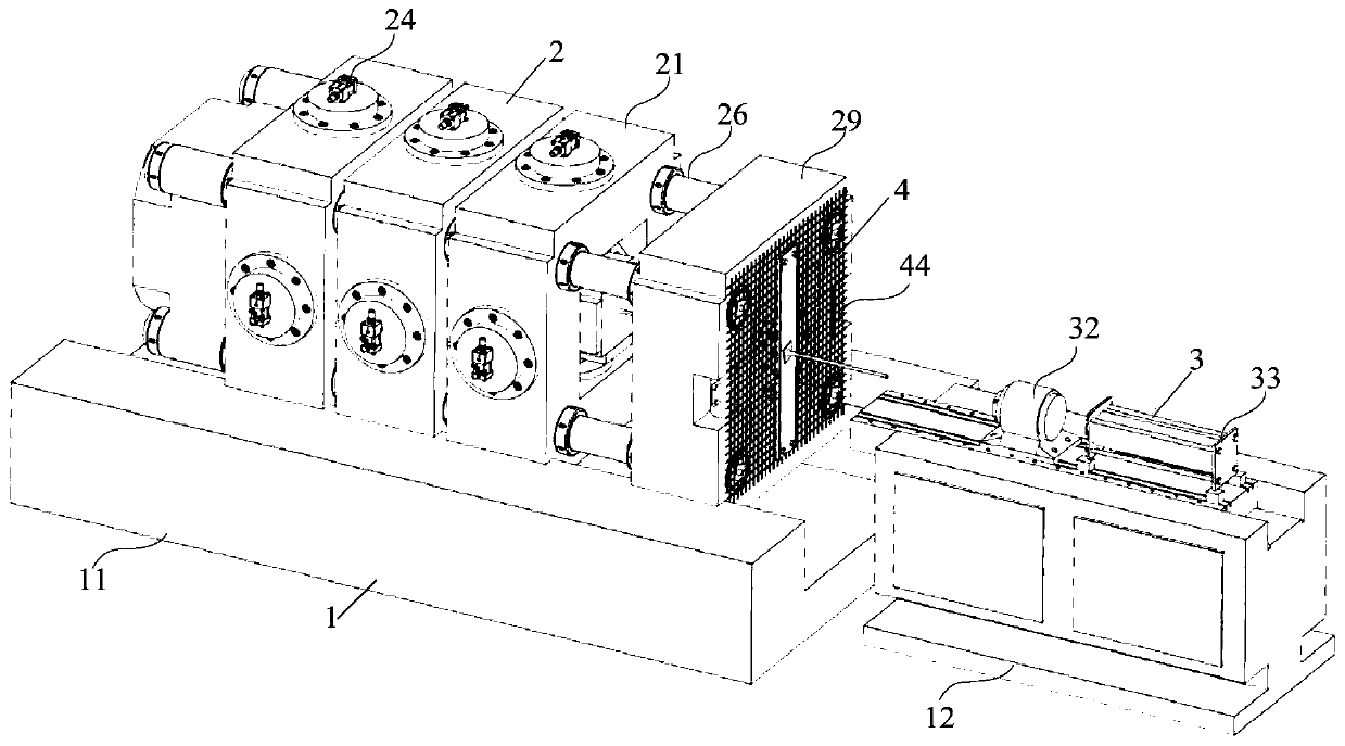
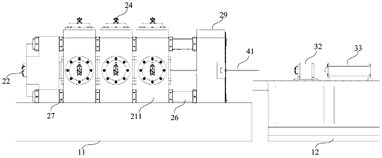
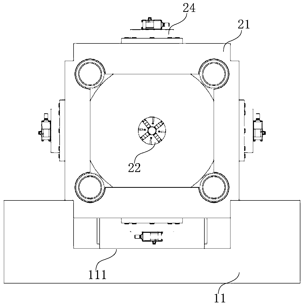
[0047] The structure of the anchor (cable) support structure test and the comprehensive test device for anchorage system performance includes a frame 1, a loading mechanism 2, a testing mechanism 3 and a test piece 4, such as Figure 1 to Figure 5 As shown, the frame 1 includes a base 11 and an operating table 12, the loading mechanism 2 includes a loading frame 21, an anchor chuck 22, a pressure bearing plate 23, a drawing hollow cylinder 31 and a plurality of loading cylinders 24, and a testing mechanism 3 Including torsion motor 32, rock bolter 33, and monitoring devices such as acoustic emission probes, stress and displacement sensors, etc., specimen 4 includes anchoring components such as test bolt 41, rock specimen 42, steel belt 43, anchor net 44, and tray 45. The device can simulate the actual ground stress conditions through the loading mechanism 2, and use the drawing hollow cylinder 31 of the testing mechanism 3 to apply tension to the test anchor 41, the torsion mot...

Embodiment 2

[0057]The structure of a bolt support structure test and anchoring system performance comprehensive test device includes a frame 1, a loading mechanism 2, a testing mechanism 3 and a test piece 4, and the frame 1 includes a base 11 and an operating table 12, and the loading mechanism 2 Including loading frame 21, anchor chuck 22, pressure bearing plate 23, drawing hollow cylinder 31 and 12 loading cylinders 24, testing mechanism 3 includes torsion motor 32 and anchor drilling machine 33, as well as stress and displacement sensors, acoustic emission probes and other monitoring devices, the test piece 4 includes a test bolt 41, a rock test piece 42, a steel belt 43, an anchor net 44 and a pallet 45.

[0058] The frame includes a base 11 and an operating table 12, the base 11 is used to fix the various parts of the loading mechanism 2, and the operating table 12 mainly assists the torsion motor 32 and the rock bolter 33 to work. The upper surface of the base 11 is provided with a...

Embodiment 3

[0074] In this embodiment, a layer-separated loading oil cylinder is set between the two-axis frames, such as Figure 15 As shown in Fig. 1, the layer-separated anchoring control of rock mass is simulated by the layer-separated loading cylinder, and the mechanism and characteristics of the layer-separated layer, as well as the supporting mechanism and supporting capacity method of the bolt are studied.

[0075] The improvement of the structure of the testing machine includes that a separation jack 5 is arranged between the biaxial frames 211, the upper part of the biaxial frames 211 slides along the pillars, and the biaxial frames 211 can slide along the through groove 111 on the base. The test steps include: First, make a simulated test piece of similar material, or take the rock on site to make a simulated test piece, polish the surface of the simulated test piece to make it smooth, match the size of the simulated test piece with the size of the space surrounded by the pressu...


PUM


Abstract

The invention provides an anchor rod (cable) supporting structure test and anchoring system performance integration test device and method and relates to the anchoring test technology field. The device comprises a frame, a loading mechanism, a test mechanism and a test piece. The frame comprises a pedestal and an operation bench. The loading mechanism includes a loading frame, a chuck, a surrounding rock stress loading oil cylinder, and a drawing hollow oil cylinder. The test mechanism includes monitoring mechanisms of a load, displacement, acoustic emission and the like. The test piece includes a rock test piece, an anchor rod (cable), an anchor net and the like. The loading mechanism and the drawing hollow oil cylinder are arranged above the pedestal, and a torsion motor and an anchor rod drilling machine are arranged on the operation bench. The rock test piece is placed between bearing plates, and one end of the anchor rod (cable) is fixed or anchored in the rock test piece through the chuck, and the other end passes through the drawing hollow oil cylinder. The device can test mechanical performance of the anchor rod (cable) and an anchoring component, can realize stress environment simulation of ''five-sided loading and one side empty'', and can carry out surrounding rock drilling response or anchoring system performance integration testing.

Description

technical field [0001] The invention relates to the technical field of anchor rod testing, and in particular provides an anchor rod (cable) support structure test and an anchoring system performance comprehensive test device, and a method for using the device for testing. Background technique [0002] At this stage, anchor support technology is widely used in engineering fields such as deep roadway and large-span underground cavern support, dam foundation and abutment reinforcement, rock and soil slope reinforcement, deep foundation pit support, water delivery and traffic tunnels, etc. On the one hand, the scientific support scheme can effectively guarantee the safety of project construction and production, and on the other hand, it can reduce costs to obtain maximum economic benefits. Experiments and engineering studies have shown that the essential function of bolts is to effectively reinforce the surrounding rock, prevent new cracks from opening in the surrounding rock an...

Claims


Application Information

Patent Timeline
IPC IPC(8): G01N3/10G01N3/22G01N3/24
CPCG01N3/10G01N3/22G01N3/24G01N2203/0017G01N2203/0021G01N2203/0025G01N2203/0048G01N2203/0053
Inventor 赵同彬李春林邢明录谭云亮赵晨王志李小亮于凤海贾敬龙
Owner SHANDONG UNIV OF SCI & TECH
Learn More