
A tri-band small patch antenna with omnidirectional and directional radiation characteristics

A technology of directional radiation and patch antenna, which is applied in the direction of antenna, antenna grounding device, radiating element structure, etc., can solve the problems of large size, complex antenna structure, and difficult manufacturing, so as to improve impedance matching, simplify complexity, The effect of simple structure

Active Publication Date: 2020-11-03
SYNERGY INNOVATION INST OF GDUT HEYUAN
View PDF7 Cites 0 Cited by
  • Summary
  • Abstract
  • Description
  • Claims
  • Application Information

AI Technical Summary

Problems solved by technology

The circular radiating patch and the floor were short-circuited with multiple symmetrically placed shorting pins, simultaneously energizing the TM 01 Die and TM 02 successfully designed a low-profile and small-sized pole-type patch antenna, but failed to achieve multi-frequency and directional radiation functions
[0006] [2] In 2018, Shuai Gao et al. published an article entitled "Low-profile dual-bandstacked microstrip monopolar patch antenna for WLAN and car-to-carcommunications" on IEEE ACCESS, proposing to use a coupling loop and a short circuit in one antenna The pins excite the TM separately 01 Die and TM 02 mode, to achieve the dual-frequency operating bandwidth of the low-profile pole-type patch antenna, but the directional radiation function has not yet been realized
[0014] (1) At present, the dual-frequency patch antennas with both omnidirectional and directional radiation modes combine different radiators and use different radiators to achieve different working bandwidths and radiation modes. The antenna structure is relatively complex and the size is relatively large;
[0015] (2) At present, the structure of stimulating the ZOR mode with omnidirectional radiation characteristics is relatively complicated, and it is difficult to process and manufacture;
[0016] (3) At present, it is difficult for a dual-frequency patch antenna with both omnidirectional and directional radiation modes to achieve independent control of omnidirectional and directional radiation modes;
[0017] (4) At present, the shape of the dual-band patch antenna with both omnidirectional and directional radiation modes is basically limited to a circle;
[0018] (5) At present, there is no tri-band patch antenna with both omnidirectional and directional radiation modes

Method used


Image

  • A tri-band small patch antenna with omnidirectional and directional radiation characteristics
  • A tri-band small patch antenna with omnidirectional and directional radiation characteristics
  • A tri-band small patch antenna with omnidirectional and directional radiation characteristics

Examples


Embodiment Construction

[0043] The present invention will be described in detail below in conjunction with the accompanying drawings and specific embodiments, and the present invention will be described in detail below in conjunction with the accompanying drawings and specific embodiments. To explain the present invention, but not as a limitation of the present invention.

[0044] It should be noted that all directional indications (such as up, down, left, right, front, back, front, back, etc.) If the relative positional relationship, movement conditions, etc. between the components change, the directional indication will also change accordingly.

[0045] In the present invention, unless otherwise specified and limited, the term "connection" should be understood in a broad sense. For example, "connection" can be a fixed connection, a detachable connection, or an integral body; it can be a mechanical connection, or It may be an electrical connection; it may be a direct connection, it may also be an i...


PUM


Abstract

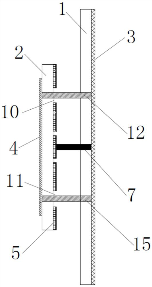
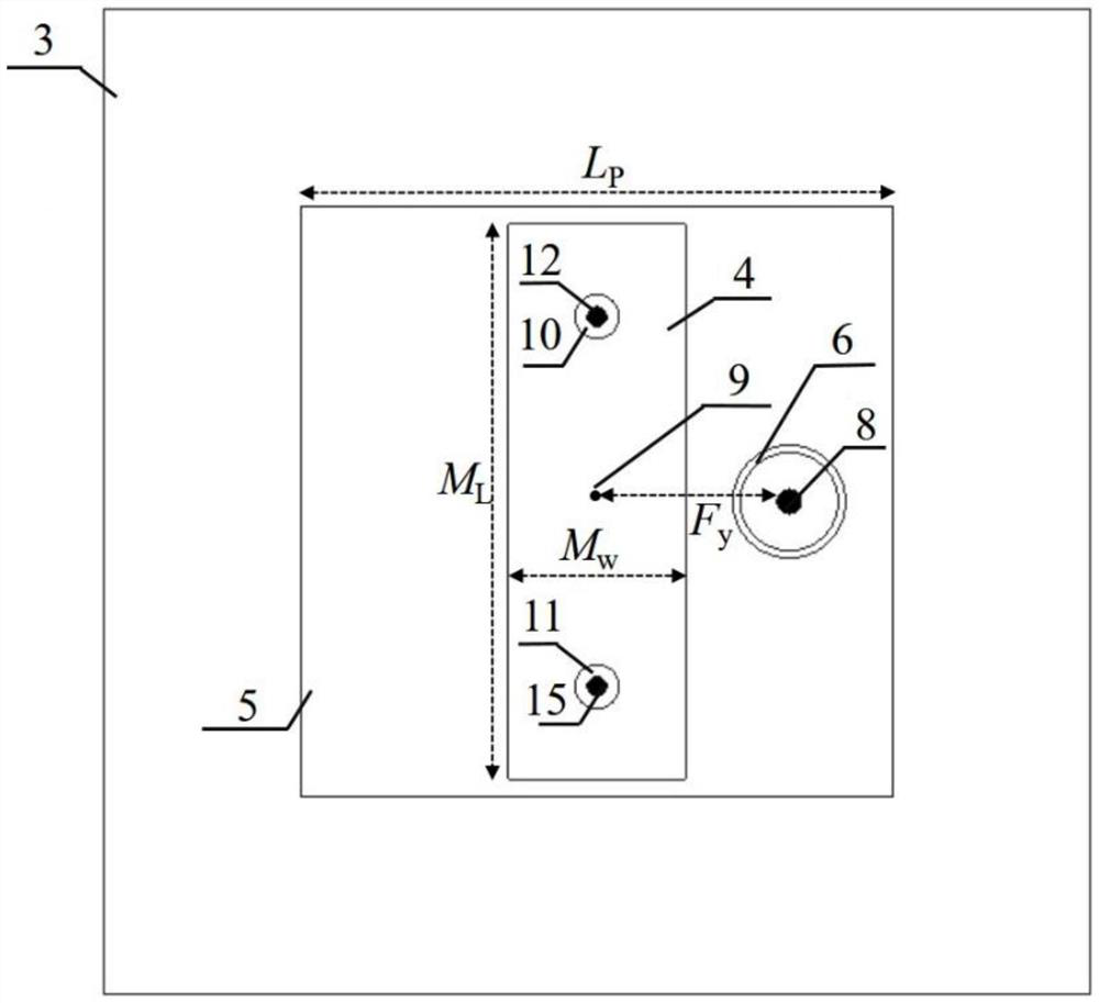
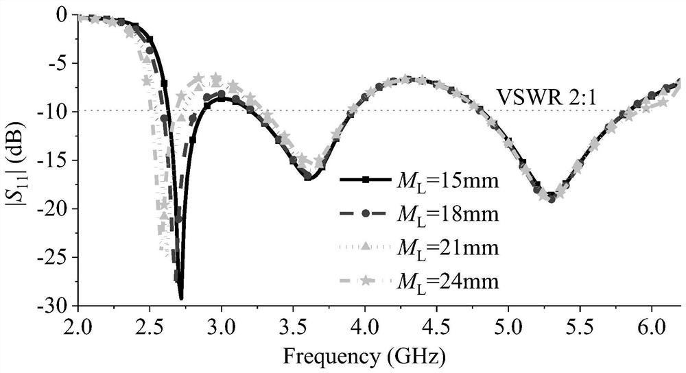
The invention discloses a three-frequency small patch antenna with omnidirectional and directional radiation characteristics. The three-frequency small patch antenna comprises a first substrate, a second substrate, a system floor, a short-circuit device, a narrow-edge metal sheet and a radiation patch, wherein the radiation patch is provided with an avoiding part and an annular groove, the narrow-edge metal sheet penetrates through the avoiding part through the short-circuit device and is connected with the system floor, so that a ZOR mode with an omnidirectional radiation characteristic is excited at a low frequency, and a first working bandwidth with the omnidirectional radiation characteristic is obtained at the low frequency. The radiation patch is connected with the system floor through a feed probe located at the circle center of the annular groove. The distance between the circle center of the annular groove and the center of the radiation patch is FY. The impedance matching of the patch antenna is improved by changing the value of the FY, so that a double TM01 mode is excited, and a second working bandwidth and a third working bandwidth with qualitative radiation characteristics are obtained at a high frequency. According to the invention, the patch antenna with multiple frequencies and omnidirectional and directional radiation modes is realized, the complexity of the antenna structure is reduced, and the size of the antenna is reduced.

Description

technical field [0001] The invention relates to the technical field of microwave antennas, in particular to a tri-frequency small patch antenna with omnidirectional and directional radiation characteristics. Background technique [0002] As the core component of the radio frequency front-end of the wireless communication system, the antenna technology has become an urgent scientific research topic. The pole-type patch antenna has the advantages of low profile, low cost, and easy fabrication of the traditional patch antenna, and at the same time has the advantages of the omnidirectional radiation coverage of the traditional pole-type antenna on its vertical axis plane. The pole-type patch antenna is especially suitable for use in small mobile terminal equipment with limited system space and requiring omnidirectional signal coverage. On the other hand, for applications such as satellite positioning and point-to-point communication, the system antenna is required to have direc...

Claims


Application Information

Patent Timeline
Patent Type & Authority Patents(China)
IPC IPC(8): H01Q1/38H01Q1/48H01Q1/50H01Q5/10H01Q5/28H01Q5/307
CPCH01Q1/38H01Q1/48H01Q1/50H01Q5/10H01Q5/28H01Q5/307
Inventor 李健凤章国豪黄国宏唐浩
Owner SYNERGY INNOVATION INST OF GDUT HEYUAN
Learn More