Low RF sheath, high flexibility multi-element array RF wave heating antenna

A high flexibility, multi-element array technology, applied in the direction of electrical components, plasma, etc., can solve the problems of low spectral component double-pass absorption efficiency, enhanced radiation loss, and increased impurity concentration, so as to improve design flexibility, flexible installation and Effect of disassembly and reduction of impurities

Active Publication Date: 2021-05-11
HEFEI INSTITUTES OF PHYSICAL SCIENCE - CHINESE ACAD OF SCI
View PDF5 Cites 0 Cited by
  • Summary
  • Abstract
  • Description
  • Claims
  • Application Information

AI Technical Summary

Problems solved by technology

It can be seen from the absorption performance of the plasma on the radio frequency wave in the tokamak, k / / The smaller spectral component double-pass absorption efficiency is very low, it will reflect back and forth multiple times in the device, it will form a coaxial mode on the plasma surface, which will lead to a significant increase in the plasma boundary temperature, but at the same time the antenna attachment The interaction between the plasma and the antenna components is intensified, and the impurity concentration increases, especially at the position where the radio frequency potential at both ends of the antenna is high, the impurity concentration is higher, the radiation loss is enhanced, and the coupling performance is also poor, which eventually leads to a decrease in the heating effect
In addition, currently existing magnetic confinement nuclear fusion devices in the world, due to space requirements, antenna assembly brings great difficulties. How to flexibly accommodate assembly requirements and take into account the increase in coupling power is currently a common practice both at home and abroad. a difficulty

Method used


Image

  • Low RF sheath, high flexibility multi-element array RF wave heating antenna
  • Low RF sheath, high flexibility multi-element array RF wave heating antenna
  • Low RF sheath, high flexibility multi-element array RF wave heating antenna

Examples


Embodiment Construction

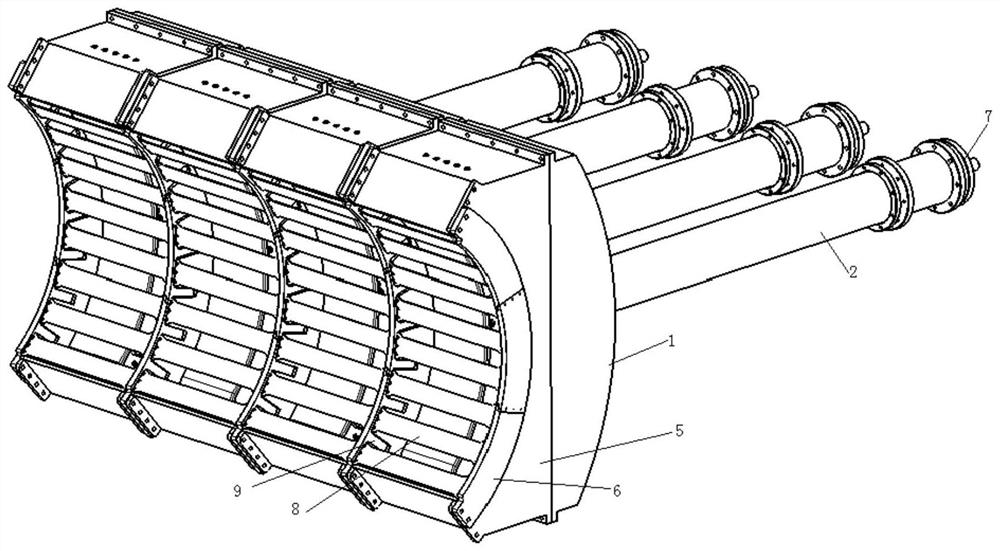
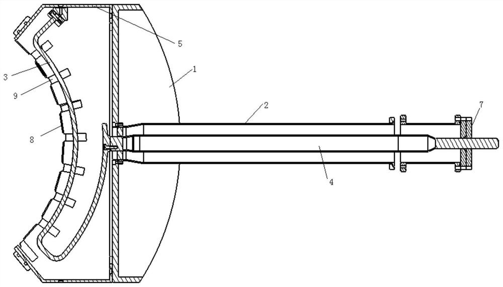
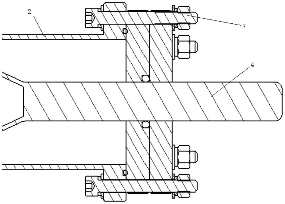
[0021] Such as figure 2 , 3 As shown, a low radio frequency sheath, high flexibility multi-element array radio frequency wave heating antenna includes a unit array antenna, and the unit array antenna includes an antenna support box 1, a Faraday shielding cavity 5, a current strip 3, an inner Conductor 4 and outer conductor 2, one end of the outer conductor 2 is fixedly connected to the back of the antenna support box 1 through a flange, the front of the antenna support box 1 is fixedly connected to the back of the Faraday shielding cavity 5, and the current The band 3 is located inside the Faraday shielding cavity 5, and one end of the current band 3 is fixed on the inner wall of the Faraday shielding cavity 5, and the inner conductor 4 passes through the outer conductor 2, the antenna support box 1 and the Faraday shielding cavity 5 and The other end of the current belt 3 is connected, and the tails of the inner conductor 4 and the outer conductor 2 are fixedly connected wi...


PUM


Abstract

The invention discloses a low radio frequency sheath and high flexibility multi-element array radio frequency wave heating antenna. One end of the outer conductor is fixedly connected to the back of the antenna support box through a flange, and the front of the antenna support box is fixed to the back of the Faraday shielding cavity. Connection, the current strip is located inside the Faraday shielding cavity, one end of the current strip is fixed on the inner wall of the Faraday shielding cavity, and the inner conductor passes through the outer conductor, the antenna support box and the Faraday shielding cavity in turn to connect with the other end of the current strip. The invention mainly heats the ion cyclotron to rotate the antenna along the tokamak magnetic field ring to the field component, reduces the potential of the radio frequency sheath at both ends of the antenna, and reduces the generation of impurities. Comb-shaped slits are set on the Faraday shielding partition to allow the field components that excite the magnetoacoustic wave to pass through unaffected, and an insulating ceramic with a high dielectric constant is designed between the Faraday shields as a limiter to avoid plasma and current. Form a path, reduce the mutual coupling between the current bands, and increase the coupling power.

Description

technical field [0001] The invention relates to the technical field of magnetic confinement nuclear fusion plasma heating, in particular to a low radio frequency sheath and high flexibility multi-element array radio frequency wave heating antenna. Background technique [0002] Ion cyclotron resonance heating (ICRH) is one of the very effective auxiliary heating means in the tokamak device, which can directly and effectively heat the ions in the plasma. Compared with low confounding waves and electron cyclotron resonance heating, the problem of improving the coupling efficiency of the antenna is very prominent due to the low operating frequency of the ion cyclotron frequency band. It can be seen from the absorption performance of the plasma on the radio frequency wave in the tokamak, k / / The smaller spectral component double-pass absorption efficiency is very low, it will reflect back and forth multiple times in the device, it will form a coaxial mode on the plasma surfac...

Claims


Application Information

Patent Timeline
Patent Type & Authority Patents(China)
IPC IPC(8): H05H1/18
CPCH05H1/18
Inventor 宋云涛杨庆喜王永胜陈肇玺徐皓赵燕平
Owner HEFEI INSTITUTES OF PHYSICAL SCIENCE - CHINESE ACAD OF SCI
Why Eureka
Try Eureka