
High-temperature and high-pressure rigidity seal ball valve for new energy industry

A high-temperature, high-pressure, hard-sealed technology, applied to shaft seals, valve details, valve devices, etc., can solve the problems of low dust cleaning efficiency, troublesome dust cleaning operation, unreasonable structural design, etc., and achieve high dust cleaning efficiency and reduce The accident rate of stuck or locked, the effect of easy dust cleaning operation

Pending Publication Date: 2019-09-27
OVIKO GRP CO LTD
View PDF0 Cites 4 Cited by
  • Summary
  • Abstract
  • Description
  • Claims
  • Application Information

AI Technical Summary

Problems solved by technology

[0002] In the new energy polysilicon production process, the hardness of silicon powder is HRC52-62, and the medium contains hydrogen, hydrogen chloride, etc. Therefore, users put forward requirements for valves such as wear resistance, corrosion resistance, and high safety; in addition, coal chemical gas , the coal-to-oil industry and the high-temperature steam cut-off in power plants also require a large number of high-quality high-end hard-sealed ball valves. However, the existing ball valves still have shortcomings: the structural design is unreasonable, and they are often prone to jamming and locking under high-temperature dust conditions. Accident; complex structure, troublesome dust cleaning operation, inconvenient maintenance, low efficiency of dust cleaning work; and the problem that the top-mounted valve stem of the existing ball valve is blown out by internal pressure, there are potential safety hazards, and the practicability is poor

Method used


Image

  • High-temperature and high-pressure rigidity seal ball valve for new energy industry
  • High-temperature and high-pressure rigidity seal ball valve for new energy industry
  • High-temperature and high-pressure rigidity seal ball valve for new energy industry

Examples


Embodiment Construction

[0019] In the description of this embodiment, it should be noted that if the terms "center", "upper", "lower", "left", "right", "vertical", "horizontal", "inner", " Outside", "front", "rear", etc., the orientation or positional relationship indicated is based on the orientation or positional relationship shown in the drawings, which is only for the convenience of describing the present invention and simplifying the description, rather than indicating or implying Any device or element must have a specific orientation, be constructed and operate in a specific orientation and, therefore, should not be construed as limiting the invention. In addition, the terms "first", "second", and "third" are used for descriptive purposes only, and should not be understood as indicating or implying relative importance.

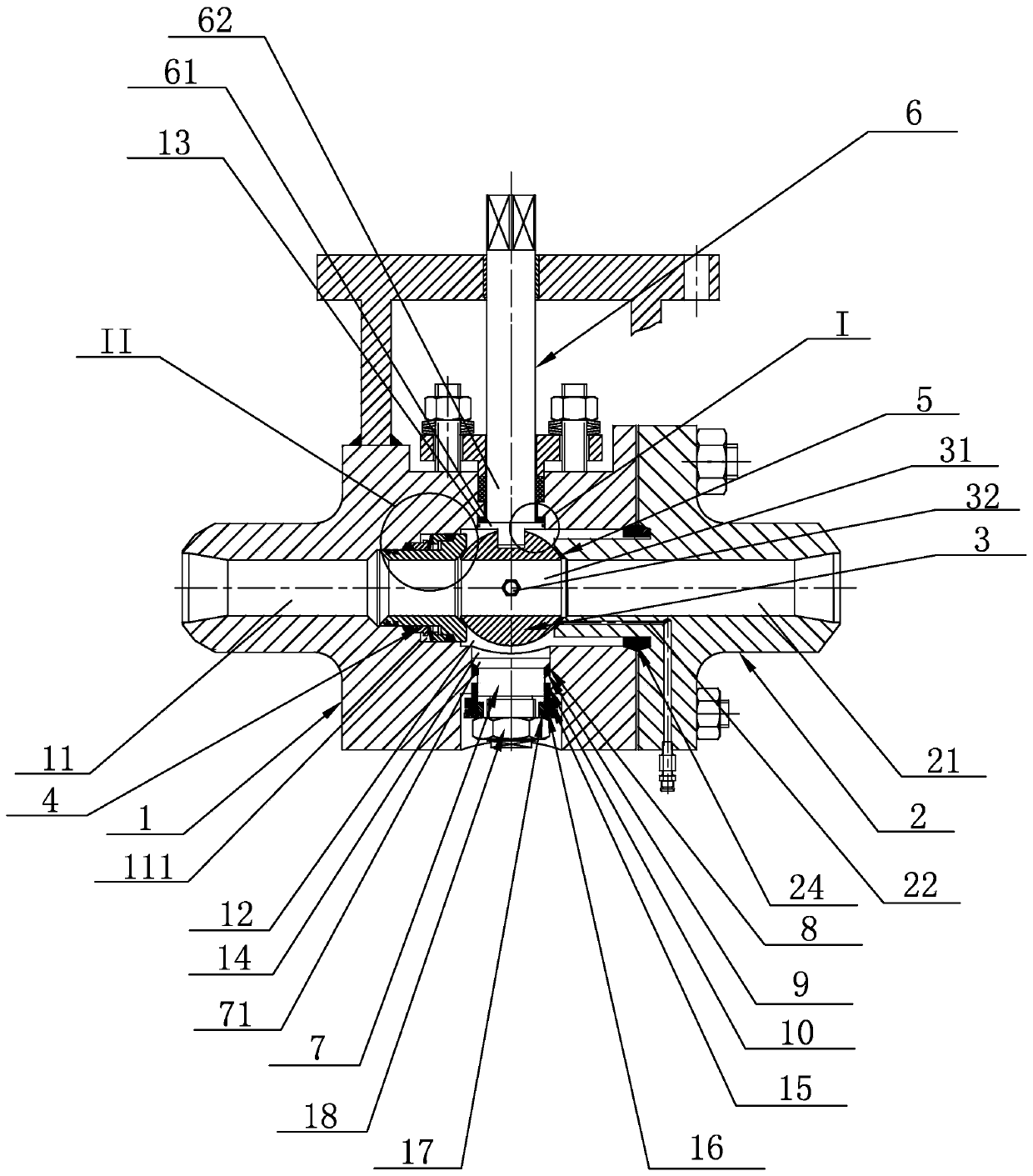
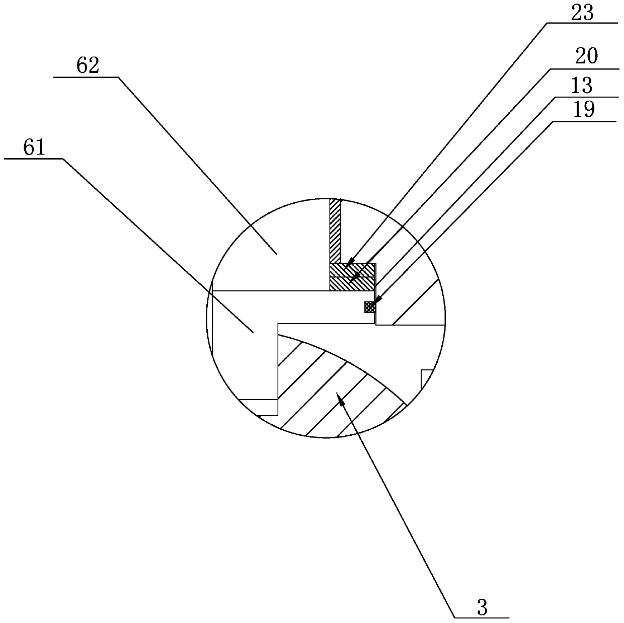
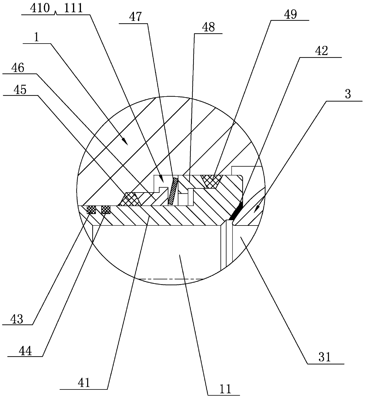
[0020] see figure 1 , figure 2 , image 3 and Figure 4 , a high-temperature and high-pressure hard-sealed ball valve for new energy industry disclosed by the present inve...


PUM


Abstract

The invention discloses a high-temperature and high-pressure rigidity seal ball valve for a new energy industry. The high-temperature and high-pressure rigidity seal ball valve comprises a left valve body and a right valve body, wherein the left valve body is internally provided with a first medium channel; the right valve body is internally provided with a second medium channel; a ball body is arranged in a valve cavity of the left valve body; an elastic valve seat assembly is arranged in a positioning groove of a left valve body valve seat; a first rigidity seal layer is welded on the right valve body; a stepped valve rod is arranged at the upper end of the ball body; a stepped hole is formed in a position, aligning to the ball body, of the upper end of the left valve body; the stepped valve rod is arranged in the stepped hole in a penetrating manner; a first dust purging hole is formed in the middle part of the left valve body and is communicated with the valve cavity; a second dust purging hole is formed in the lower end of the right valve body and is communicated with a circular groove in the first rigidity seal layer. By adopting the technical scheme, the high-temperature and high-pressure rigidity seal ball valve has the advantages that reasonable structural design, simple structure and stable work are realized; the accident rate of blocking or locking under the work conditions of high-temperature dust is effectively reduced; dust is easy to clean and high in cleaning efficiency; the convenience in maintenance, safety and reliability are realized; the valve rod cannot be blown out.

Description

technical field [0001] The invention relates to the technical field of valves, in particular to a high-temperature and high-pressure hard-sealed ball valve used in the new energy industry. Background technique [0002] In the new energy polysilicon production process, the hardness of silicon powder is HRC52-62, and the medium contains hydrogen, hydrogen chloride, etc. Therefore, users put forward requirements for valves such as wear resistance, corrosion resistance, and high safety; in addition, coal chemical gas , the coal-to-oil industry and the high-temperature steam cut-off in power plants also require a large number of high-quality high-end hard-sealed ball valves. However, the existing ball valves still have shortcomings: the structural design is unreasonable, and they are often prone to jamming and locking under high-temperature dust conditions. Accidents; complex structure, troublesome dust cleaning operation, inconvenient maintenance, low dust cleaning efficiency; a...

Claims


Application Information

Patent Timeline
IPC IPC(8): F16K5/06F16K5/08F16K5/20F16K27/06F16K41/02B08B9/032
CPCF16K5/0605F16K5/0647F16K5/0694F16K5/0689F16K5/08F16K5/201F16K27/067B08B9/0321
Inventor 邵力平陈忠信母泽冰陈芳芳徐林娟林时艳王业先邵佳慧邵磊江凯其他发明人请求不公开姓名
Owner OVIKO GRP CO LTD
Learn More