Electric-magnetic field synergetic enhancement high-power pulse magnetron sputtering deposition device and method

A high-power pulse, magnetron sputtering technology, applied in the field of coating, can solve the problems of low electron utilization rate and deposition rate ion ionization rate, and achieve the effect of improving electron utilization efficiency, increasing deposition rate and realizing simple process.

Inactive Publication Date: 2019-10-01
NORTHEAST FORESTRY UNIVERSITY
View PDF0 Cites 7 Cited by
  • Summary
  • Abstract
  • Description
  • Claims
  • Application Information

AI Technical Summary

Problems solved by technology

[0008] The purpose of the present invention is to solve the problems of low electron utilization rate, deposition rate and ion ionization rate in the current high-power pulse magnetron sputtering method. The present invention provides an electric-magnetic field synergistically enhanced high-power pulse magnetron sputtering deposition Device and method

Method used


Image

  • Electric-magnetic field synergetic enhancement high-power pulse magnetron sputtering deposition device and method

Examples


specific Embodiment approach 1

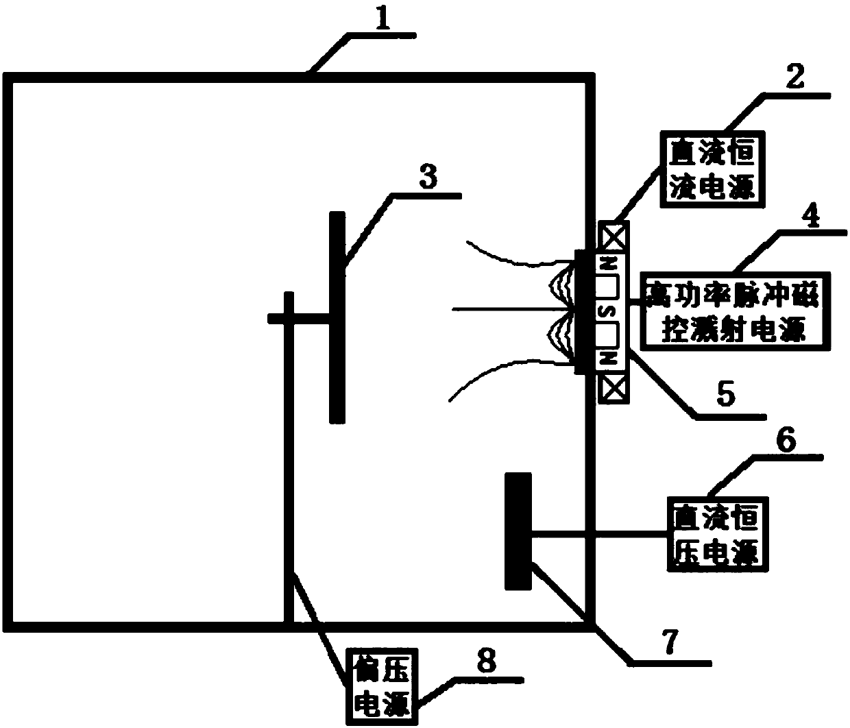
[0023] Specific implementation mode one: combine figure 1 Describe this embodiment, the electric-magnetic field synergistically enhanced high-power pulse magnetron sputtering deposition device described in this embodiment, the deposition device includes a vacuum chamber 1, a workpiece frame 3, a high-power pulse magnetron sputtering power supply 4, a cathode Magnetron target 5 and bias power supply 8; Bias power supply 8 provides bias voltage for workpiece holder 3 in vacuum chamber 1, and high-power pulse magnetron sputtering power supply 4 supplies power for cathode magnetron target 5, and the cathode magnetron target 5 provides a permanent magnetic field for the vacuum chamber 1;

[0024] It is characterized in that the deposition device also includes a DC constant current power supply 2, a DC constant voltage power supply 6, an auxiliary anode 7 and an excitation coil; the excitation coil is wound on the outside of the cathode magnetron target 5, and the DC constant curren...

specific Embodiment approach 2

[0025] Embodiment 2: This embodiment is the deposition method of the electric-magnetic field synergistically enhanced high-power pulse magnetron sputtering deposition device described in Embodiment 1. The deposition method includes the following steps:

[0026] Step 1 and Step 2 are performed separately, and then Step 3 is performed:

[0027] Step 1: Build electric field enhanced high power pulsed magnetron discharge:

[0028] The high-power pulse magnetron sputtering power supply 4 and the bias power supply 8 work. By adjusting the position of the auxiliary anode in the vacuum chamber 1 and controlling the output voltage of the DC constant voltage power supply 6, the trajectory of the electrons is changed so that the electrons reach the deposition area. Thereby determine the magnitude of the voltage output by the DC constant voltage power supply 6 and the position of the auxiliary anode in the vacuum chamber 1;

[0029] In this step, when the high-power pulse magnetron sputt...


PUM


Abstract

The invention discloses an electric-magnetic field synergetic enhancement high-power pulse magnetron sputtering deposition device and method, and belongs to the technical field of coating. In order tosolve the problems that according to an existing high-power pulse magnetron sputtering method, the electron utilization rate is low, the deposition rate during coating is low, and system particle ionization rate remains to be further increased, according to the deposition device, an excitation coil is wound around the outer side of a cathode magnetic control target, a direct current and constantcurrent power source supplies continuous and adjustable current to the excitation coil at the outer side of the cathode magnetic control target, an auxiliary anode is placed into a vacuum chamber, anda direct current and constant voltage power source supplies continuous and adjustable voltage to the auxiliary anode inside the vacuum chamber; according to the deposition method of the deposition device, the coaxial excitation coil is used for optimizing distribution of a magnetic field in front of the cathode magnetic control target, meanwhile, the auxiliary anode is used for controlling distribution of an electric field/potential inside the vacuum chamber, directional electron pulling and restraining can be achieved, then, the purposes of improving the electron utilizing rate of the high-power pulse magnetron sputtering technology and the deposition rate and further increasing the system particle ionization rate can be achieved, and a high-quality coating is deposited. The electric-magnetic field synergetic enhancement high-power pulse magnetron sputtering deposition device and method can be used for the technical field of coatings.

Description

technical field [0001] The invention belongs to the technical field of coating, and in particular relates to an electric-magnetic field synergistically enhanced high-power pulse magnetron sputtering deposition device and method. Background technique [0002] Physical vapor deposition technology is a common technology for preparing hard coatings. It has the advantages of low deposition temperature (200 ° C), wide application range of substrates, and easy control of film quality. The representative one is magnetron sputtering. Radiation technology and multi-arc ion plating technology. Magnetron sputtering technology has the advantages of high deposition rate, but its sputtering metal ionization rate is low and has the disadvantages of non-dense film layer and poor film / substrate bonding strength; while multi-arc ion plating technology although metal ionization rate Higher, but there is often the problem of "big particles", which leads to the deterioration of the surface quali...

Claims


Application Information

Patent Timeline
Patent Type & Authority Applications(China)
IPC IPC(8): C23C14/35
CPCC23C14/345C23C14/3485C23C14/355
Inventor 李春伟
Owner NORTHEAST FORESTRY UNIVERSITY
Why Eureka
Try Eureka