Low-nitrogen burner and fuel gas device thereof

A low-nitrogen burner and air technology, which is applied to burners, gas fuel burners, combustion methods, etc., can solve the problems of unfavorable low-nitrogen environmental protection emission requirements, difficult product performance stability, and high gas emissions, so as to improve energy Conversion efficiency, achieving low nitrogen oxide emissions, and reducing CO emissions

Inactive Publication Date: 2019-10-01
GUANGDONG VANWARD NEW ELECTRIC CO LTD
View PDF1 Cites 2 Cited by
  • Summary
  • Abstract
  • Description
  • Claims
  • Application Information

AI Technical Summary

Problems solved by technology

[0002] Most of the existing burner technologies are ordinary atmospheric burners, NO X Gas (nitrogen oxides) emissions are high, which is not conducive to low-nitrogen environmental protection emission requirements. At present, gas water heaters and gas wall-hung boilers in European countries have compulsorily implemented low-nitrogen oxide emission requirements. It is foreseeable that China will also move towards low-nitrogen emissions in the near future. direction development
At present, thick-lean combustion technology is used in the industry to achieve low nitrogen oxide emissions, but most of the existing thick-lean burners adopt a structure with double ejectors. For example, a low-nitrogen burner is disclosed in Chinese patent application No. 201610526887.7. Including mixers, etc. The mixer includes a cylinder and an inner cylinder. The inner cylinder is equipped with a combustion-supporting air swirl vane, an air inlet cylinder, and a swirl impeller to ensure uniform combustion and low nitrogen oxide emissions. The disadvantages are that the structure is complicated, the manufacturing is troublesome, the cost is high, and the control is inconvenient, so it is difficult to ensure the stability of product performance

Method used


Image

  • Low-nitrogen burner and fuel gas device thereof
  • Low-nitrogen burner and fuel gas device thereof
  • Low-nitrogen burner and fuel gas device thereof

Examples


Embodiment Construction

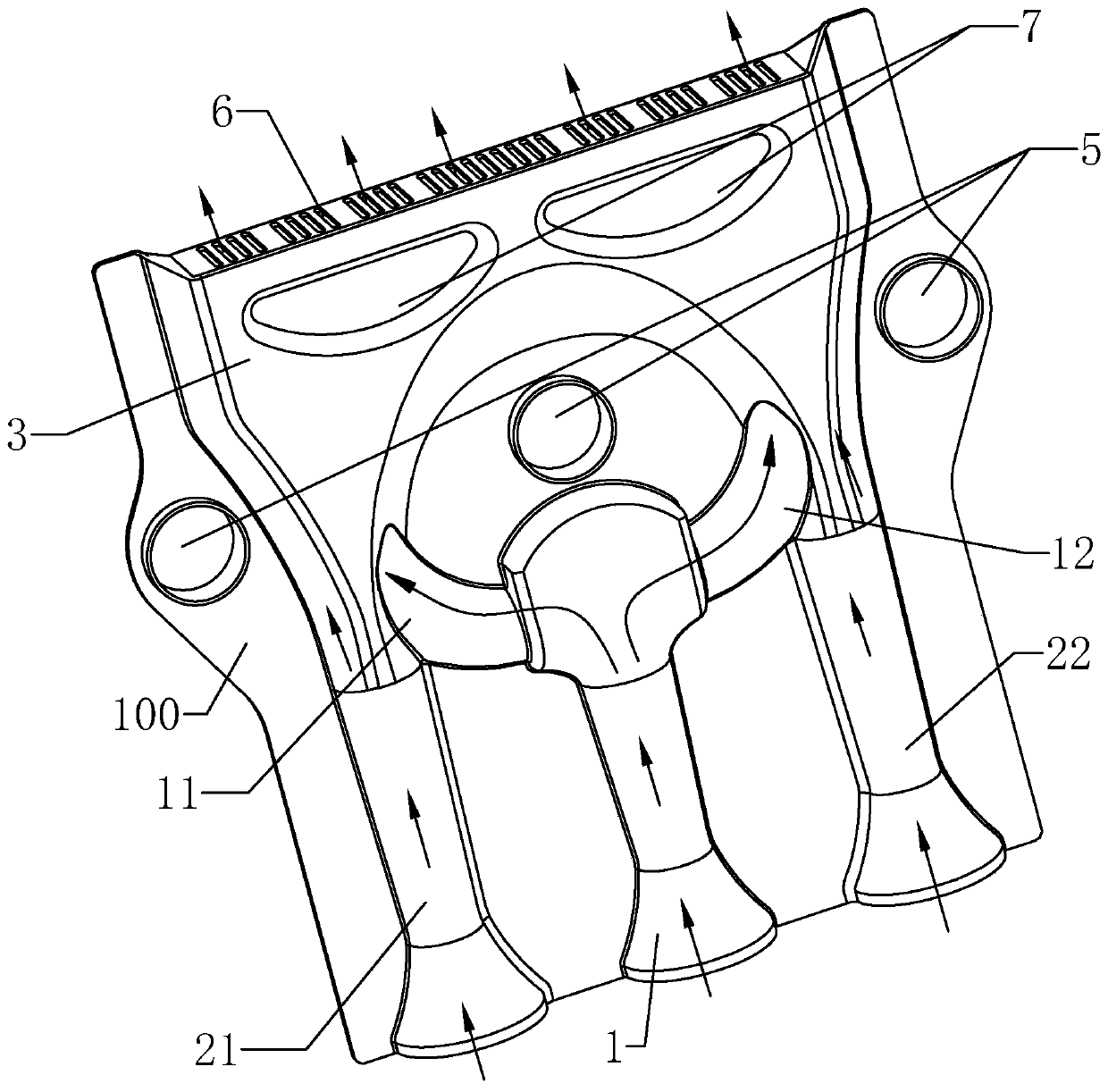
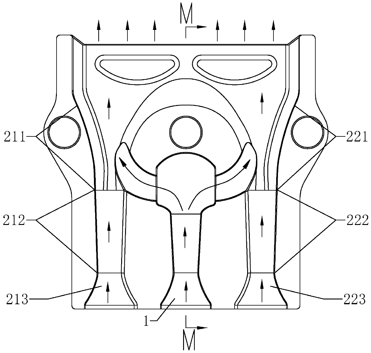
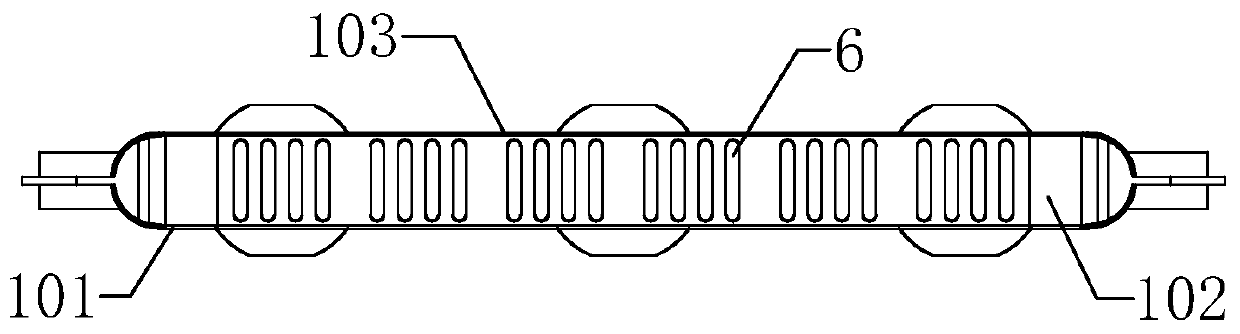
[0012] combine Figure 1 to Figure 4 , a low-nitrogen burner, including a housing 100, the housing 100 is provided with an injection channel 1, a split channel (11, 12), an air supply channel (21, 22), a diffusion mixing chamber 3, and the housing 100 There are also three water flow channels 5 arranged through the thickness direction; the air inlet of the injection channel 1 is used to introduce gas and air, and the gas outlet end of the injection channel 1 passes through the shunt channel (11, 12) and the air supply channel ( 21, 22), the diffuser mixing chamber 3 communicates, the air inlet of the air supply passage (21, 22) is used to introduce air, the air outlet of the air supply passage (21, 22) communicates with the diffuser mixing chamber 3, and the housing 100 A fire outlet 6 communicating with the diffuser mixing chamber 3 is provided on the top of the tank.

[0013] The present invention is provided with an injection channel 1, and the gas nozzle is correspondingly...


PUM


Abstract

The invention relates to a low-nitrogen burner and a fuel gas device thereof. The low-nitrogen combustor comprises a shell, wherein an injection channel, an air supply channel, a diversion channel anda diffusion mixing cavity are arranged in the shell, the shell is further provided with a plurality of water flow channels which are arranged in the thickness direction in a penetrating manner; the gas inlet of the injection channel is used for introducing fuel gas and air, the air outlet end of the injection channel is in communication with the air supply channel through the diversion channel, an air inlet of the air supply channel is used for introducing air, an air outlet of the air supply channel is in communication with the diffusion mixing cavity, and the top of the shell is provided with a fire outlet communicating with the diffusion mixing cavity. According to the low-nitrogen burner and the fuel gas device thereof, the emission of the low nitrogen oxide can be effectively realized, the structure is relatively simple, and the control is facilitated.

Description

technical field [0001] The invention relates to a low-nitrogen burner and its gas device, in particular to a low-nitrogen burner and its gas device capable of realizing low nitrogen oxide discharge. Background technique [0002] Most of the existing burner technologies are ordinary atmospheric burners, NO X Gas (nitrogen oxides) emissions are high, which is not conducive to low-nitrogen environmental protection emission requirements. At present, gas water heaters and gas wall-hung boilers in European countries have compulsorily implemented low-nitrogen oxide emission requirements. It is foreseeable that China will also move towards low-nitrogen emissions in the near future. direction development. At present, thick-lean combustion technology is used in the industry to achieve low nitrogen oxide emissions, but most of the existing thick-lean burners adopt a structure with double ejectors. For example, a low-nitrogen burner is disclosed in Chinese patent application No. 201610...

Claims


Application Information

Patent Timeline
Patent Type & Authority Applications(China)
IPC IPC(8): F23D14/04F23D14/62
CPCF23D14/04F23D14/62
Inventor 卢楚鹏张上兵李罗标潘同基唐元锋
Owner GUANGDONG VANWARD NEW ELECTRIC CO LTD
Why Eureka
Try Eureka