
A mim waveguide structure based on hybrid high quality factor

A waveguide structure, high-quality technology, applied in light guides, instruments, optics, etc., can solve problems such as Q factor instability, achieve stable Q factor, high sensitivity, and improve Q factor

Active Publication Date: 2021-02-26
雄芯光电科技有限责任公司
View PDF7 Cites 0 Cited by
  • Summary
  • Abstract
  • Description
  • Claims
  • Application Information

AI Technical Summary

Problems solved by technology

[0005] In view of the above problems, the purpose of the present invention is to solve the problem of unstable Q factor that exists when the optical waveguide device of the existing guided wave optical system performs waveguide coupling.

Method used


Image

  • A mim waveguide structure based on hybrid high quality factor
  • A mim waveguide structure based on hybrid high quality factor
  • A mim waveguide structure based on hybrid high quality factor

Examples


Embodiment 1

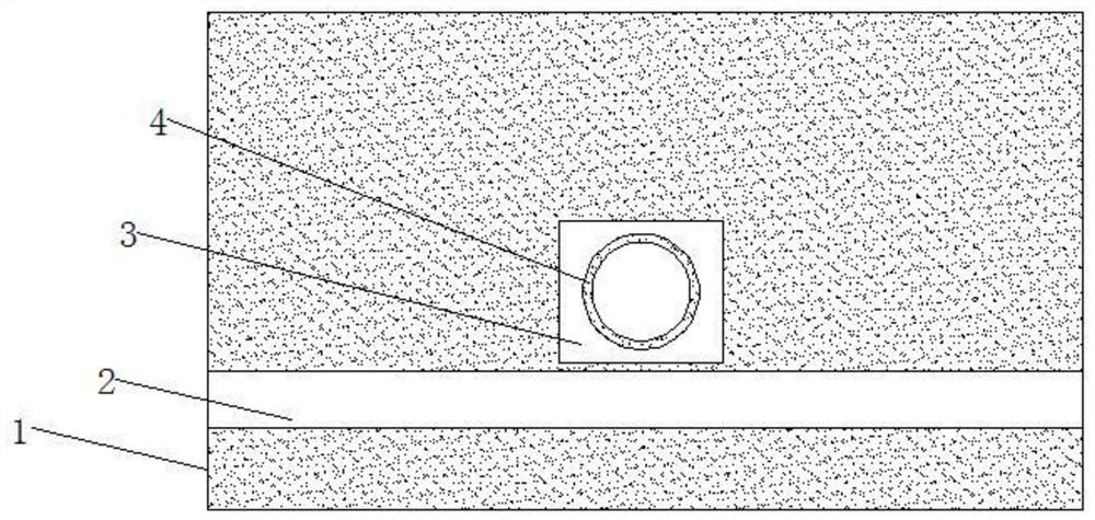
[0029] In order to solve the defect that the Q factor is unstable when the optical waveguide device of the existing waveguide optical system performs waveguide coupling. This embodiment provides a figure 1 The MIM waveguide structure based on the hybrid high quality factor shown includes a main body 1, an optical channel 2 is arranged above the main body 1; a first resonant cavity 3 is arranged above the optical channel 2; the first resonant A first resonant ring 4 is set in the cavity 3; when light enters the optical channel 2 from the entrance at the left end, surface plasmons will be excited in the optical channel 2, and are connected with the first resonant cavity 3 above, the first The resonant ring 4 is coupled, and the first resonant cavity 3 and the first resonant ring 4 each generate different plasmon resonances, and the different plasmon resonances are combined to form a hybrid plasmon resonance, so that the The MIM waveguide structure has a high Q factor, and the M...

Embodiment 2

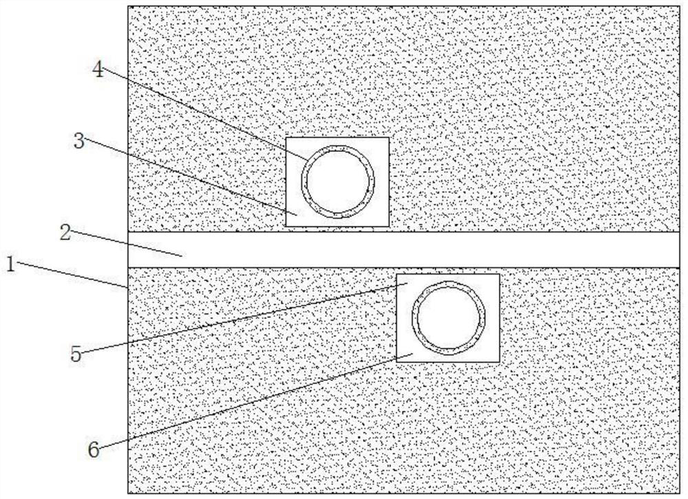
[0036] The embodiment provides a method such as figure 2 The MIM waveguide structure based on the hybrid high quality factor shown includes a main body 1, an optical channel 2 is arranged above the main body 1; a first resonant cavity 3 is arranged above the optical channel 2; the first resonant A first resonant ring 4 is provided in the cavity 3; a second resonant cavity 5 is provided below the optical channel 2; a second resonant ring 6 is provided in the second resonant cavity 5; the first resonant ring 4 and The axes of the second resonant ring 6 are parallel. When the light enters the optical channel 2 from the entrance at the left end, the surface plasmons will be excited in the optical channel 2, and will interact with the first resonant cavity 3 above, the first resonant ring 4, and the second resonant cavity 5 above. , the second resonant ring 6 are coupled, and the first resonant cavity 3, the first resonant ring 4, the second resonant cavity 5, and the second reso...

Embodiment 3

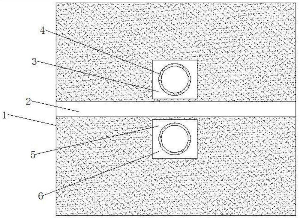
[0040] On the basis of Example 2, such as image 3 As shown, the first resonant cavity 3 and the second resonant cavity 5 are asymmetrically arranged with the optical channel 2 as an asymmetrical axis, the resonance modes of the two resonant cavities are superimposed on each other, and the phase is adjusted by the distance to form a more complex Fano resonance, which has a good effect on refraction rate changes are more sensitive; if Figure 7 Shown is the transmission spectrum of the MIM waveguide structure based on the hybrid high quality factor.


PUM


Abstract

The invention relates to an MIM (Metal-Insulator-Metal) waveguide structure based on a hybrid high-quality factor. The structure comprises a main body, wherein a light path is arranged above the mainbody; a first resonant cavity is arranged above the light path; and a first resonant ring is arranged in the first resonant cavity. The MIM waveguide structure based on the hybrid high-quality factorhas the advantages of small volume, easiness in integration and high sensitivity. A square ring is arranged in the main body, a round ring is arranged in the square ring so as to form different plasmon resonances, the hybrid plasmon resonance is formed, the type of the generated resonance is stable, so that the Q factor of the waveguide is improved, and therefore, the Q factor of the waveguide isstable.

Description

technical field [0001] The invention belongs to the technical field of waveguide structures, and in particular relates to a MIM waveguide structure based on a hybrid high quality factor. Background technique [0002] Based on the electromagnetic theory of light, guided wave optics studies the effects of propagation, scattering, polarization, and diffraction of light waves in optical waveguides, and has become the theoretical basis for various optical waveguide devices and fiber optic technologies. Usually people divide the research of optical fiber and other guided wave optics into two different fields, namely fiber optics and integrated optics, but their theoretical basis is the same, which is guided wave optics. [0003] A guided wave optical system generally consists of a light source, a coupler, an optical waveguide device, an optical modulator, and an optical detector. Compared with traditional, non-integrated discrete optical component systems, guided wave optical sys...

Claims


Application Information

Patent Timeline
Patent Type & Authority Patents(China)
IPC IPC(8): G02B6/293
CPCG02B6/29337
Inventor 不公告发明人
Owner 雄芯光电科技有限责任公司
Learn More