
Contact type liquid nitrogen cryotherapy device

A technology of liquid nitrogen freezing and treatment equipment, applied in the field of skin disease treatment and beauty, can solve the problems of unclear freezing temperature, hypoxia and suffocation of patients, and the temperature that cannot reach liquid nitrogen, so as to avoid the battle between doctors and patients.

Pending Publication Date: 2019-10-08
海尔生物医疗科技(成都)有限公司
View PDF0 Cites 0 Cited by
  • Summary
  • Abstract
  • Description
  • Claims
  • Application Information

AI Technical Summary

Problems solved by technology

Direct injection of low-temperature nitrogen gas during facial treatment may easily cause the risk of hypoxia and suffocation due to excessive inhalation of nitrogen gas by the patient (nitrogen gas is an inert gas and cannot be breathed), and the nitrogen injection area is too large to be directional frozen. The skin freezes together, causing damage from overfreezing
[0003] The contact type of the current liquid nitrogen freezing equipment is to use a tapered copper head or a cotton swab to soak it in liquid nitrogen and then press it on the skin to freeze it, because the liquid nitrogen has a low boiling point and is easy to vaporize the copper head or cotton swab taken out of the liquid nitrogen. The temperature will rise quickly, and the temperature in contact with the skin generally does not reach the temperature of liquid nitrogen, and the temperature will become higher and higher after contact with the skin, so that it is not clear what the freezing temperature is, and it feels that the temperature is not enough and starts again. Change a copper head or cotton swab; the use of this kind of cryotherapy equipment mainly depends on the experience of the operator, and it is easy to cause insufficient freezing and excessive freezing (frost injury)

Method used


Image

  • Contact type liquid nitrogen cryotherapy device
  • Contact type liquid nitrogen cryotherapy device
  • Contact type liquid nitrogen cryotherapy device

Examples


Embodiment 1

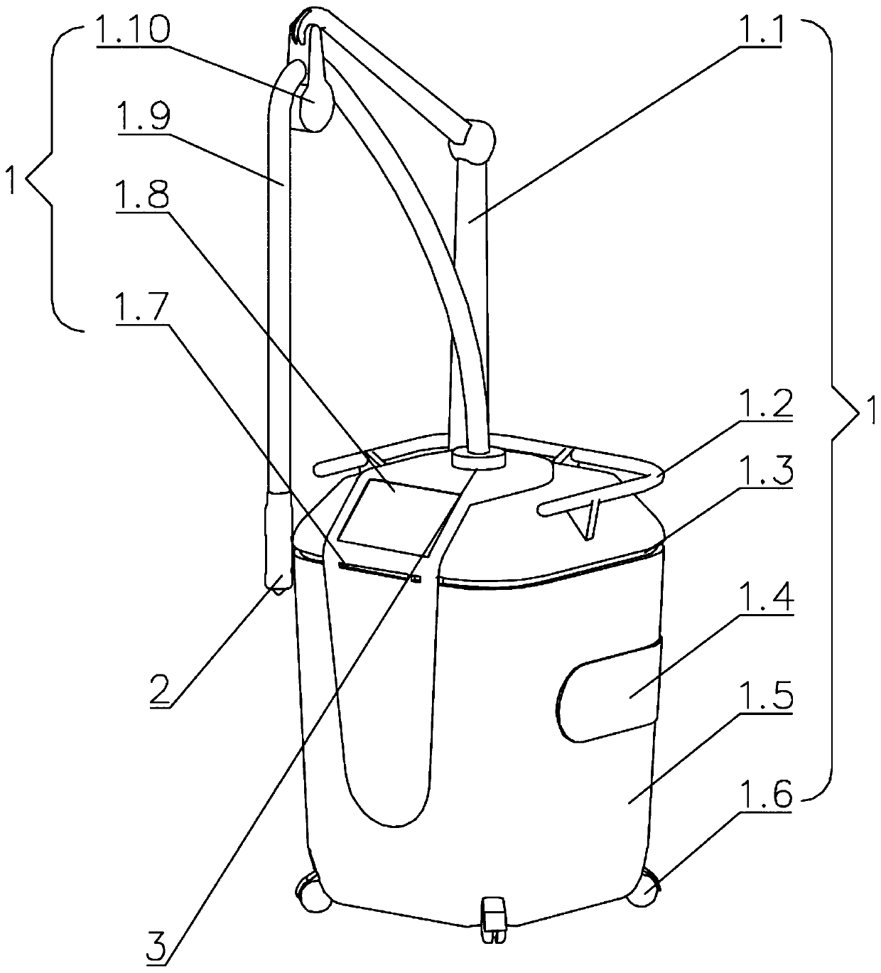
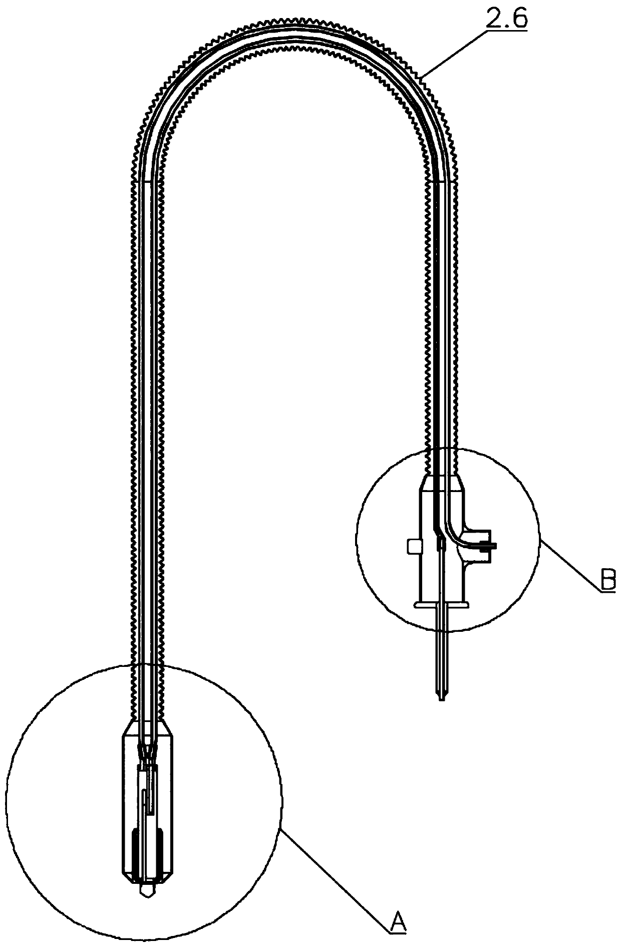
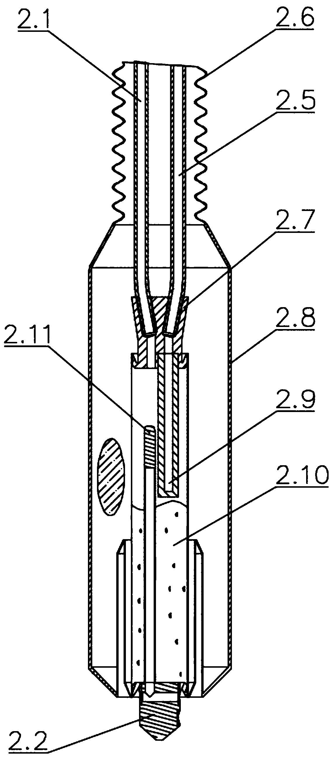
[0037] As shown in the figure, a contact type liquid nitrogen cryotherapy equipment includes an outer layer mechanism 1, an implementing mechanism 2, and an inner layer mechanism 3. The outer layer mechanism 1 is arranged outside the inner layer mechanism 3, and the implementing mechanism 2 is connected with the inner mechanism 3; the implementing mechanism 2 includes a gas phase tube 2.1, a frozen head 2.2, a vacuum male joint 2.3, a ferrule flange 2.4, a liquid phase tube 2.5, a stainless steel thin-walled tube 2.6, an inner tube seat 2.7, and an outer shell 2.8, phase separator 2.9, liquid effusion device 2.10, temperature probe 2.11, transition tube 2.12, vacuum interface 2.13, tee shell 2.14, the ends of the gas phase tube 2.1 and liquid phase tube 2.5 are inserted in the upper part of the shell 2.8, the The gas phase tube 2.1 and the liquid phase tube 2.5 are arranged in the stainless steel thin-walled tube 2.6, the end of the gas phase tube 2.1 and the end of the liquid ...

Embodiment 2

[0041] As shown in the figure, the ends of the liquid phase tube 2.5 and the gas phase tube 2.1 are processed with a section of external thread by a die, and the surface of the thread is coated with low-temperature glue and screwed into the internal thread of the inner pipe seat 2.7 made of stainless steel. Low-temperature glue is used for sealing; the bottom liquid nitrogen outlet of the inner pipe seat 2.7 is connected to the phase separator 2.9, and the liquid nitrogen injected through the liquid phase pipe 2.5 passes through the dense micropores in the phase separator 2.9. Nitrogen naturally gathers downwards in the lower half of the liquid accumulator 2.10, and the nitrogen is transported upward by the gas phase pipe 2.1 and discharged to the outside of the liquid nitrogen container 3.6 through the exhaust port 1.4; the temperature probe 2.11 is installed on the frozen head 2.2, and the probe It is located in the upper part of the liquid accumulator 2.10; the liquid nitrog...

Embodiment 3

[0043] As shown in the figure, the liquid nitrogen container 3.6 with high-vacuum multi-layer insulation is used to store liquid nitrogen, and the liquid nitrogen in the liquid nitrogen container 3.6 measures the pressure through the pressure sensor 3.8 and feeds the measured data back to the touch screen controller 1.8 , the controller judges the start / stop of the heater 3.11 according to the comparison between the measured value and the set value, the liquid nitrogen is vaporized by the heater 3.11 to increase the pressure in the container, and the pressure heater 3.11 does not start when the required pressure is reached, and the pressure exceeds When high, the safety valve 3.4 is opened to release the pressure; the pressure gauge 3.3 is mechanically used for pressure display when the power supply is not turned on, and the capacitance liquid level gauge 3.9 measures the height of the liquid nitrogen liquid level in the container. When the liquid level height is low When setti...


PUM


Abstract

The invention discloses a contact type liquid nitrogen cryotherapy device. The contact type liquid nitrogen cryotherapy device comprises an outer layer mechanism, an implementing mechanism and an inner layer mechanism. The outer layer mechanism is arranged on the outer side of the inner layer mechanism, and the implementing mechanism is connected with the inner layer mechanism; according to the size of an area need to be treated, cryoprobes of different sizes are selected and unnecessary damages to skin in a non-treatment area cannot be caused; one end of the cryoprobe is in contact with the skin and the other end of the cryoprobe is always in contact with liquid nitrogen so that the liquid nitrogen temperature is directly transmitted to the skin; and a temperature sensor with a patch is arranged on the cryoprobe to monitor the temperature of the cryoprobe in real time in the freezing process, so that it is ensured that the temperature of the cryoprobe is low enough and stable; in thefreezing process, the temperature is not judged by relying on the sense of a patient; nitrogen vaporized from liquid nitrogen or nitrogen which is not directly sprayed to the skin is collected by a pipeline and discharged separately, and the freezing safety is high; and the freezing temperature can be recorded in a storage of the device or even printed out by a printer provided with the device andsigned by both doctors and patients to avoid doctor-patient fights afterwards.

Description

technical field [0001] The invention relates to the technical fields of skin disease treatment and cosmetology, in particular to a contact-type liquid nitrogen cryotherapy device. Background technique [0002] Now liquid nitrogen freezing equipment is non-contact by vaporizing liquid nitrogen and spraying low-temperature nitrogen onto the skin surface for cryotherapy. The temperature of nitrogen is generally not lower than -150°C, and the temperature under liquid nitrogen (-196°C) is not really realized. ℃) treatment; for stubborn skin diseases and skin cosmetics requiring low temperature, the temperature treatment effect of -196 ℃ is better. Direct injection of low-temperature nitrogen gas during facial treatment may easily cause the risk of hypoxia and suffocation due to excessive inhalation of nitrogen gas by the patient (nitrogen gas is an inert gas and cannot be breathed), and the nitrogen injection area is too large to be directional frozen. The skin freezes together,...

Claims


Application Information

Patent Timeline
IPC IPC(8): A61B18/02
CPCA61B18/02A61B2018/00452A61B2018/00791
Inventor 叶敏唐文明
Owner 海尔生物医疗科技(成都)有限公司
Learn More