
Brushless synchronous generator salient pole exciter stator and manufacturing method thereof

A synchronous generator, salient-pole technology, applied in the manufacture of motor generators, stator/rotor bodies, magnetic circuits, etc., can solve the problem of cumbersome process, not much improvement, increase in size and weight of generators, etc. problem, to achieve the effect of obvious downward trend, improved response speed, and improved dynamic characteristics

Pending Publication Date: 2019-10-08
ZHENJIANG ZHONGCHUAN XIANDAI GENERATING EQUIP CO LTD
View PDF0 Cites 0 Cited by
  • Summary
  • Abstract
  • Description
  • Claims
  • Application Information

AI Technical Summary

Problems solved by technology

[0005] 1. For long-term generators under working conditions (such as emergency generators), it is necessary to magnetize the exciter stator before it can generate electricity normally when it is running again. The process is cumbersome and affects the emergency response speed
[0006] 2. After the generator is manufactured, its transient reactance parameters and inherent characteristics have been solidified. When there is a large deviation between the actual value and the design value, the dynamic performance of the generator may not meet the standards or user requirements. At this time If only by adjusting the response mode (PID) parameters between the output and input of the excitation system, there is not much improvement
[0008] At present, the solution to problem 1 is to increase the permanent magnet auxiliary exciter, the solution to problem 2 is to increase the redundancy design of the main generator, and the solution to problem 3 is to replace the AVR with a larger range. Although these solutions can solve the loss of excitation , dynamic characteristics and excitation current exceed the range of AVR, but this increases the size and weight of the generator, which greatly increases the manufacturing cost of the generator
The existing 50kW, 400V brushless synchronous generator directly starts the 27.5kW fan with a pressure drop of 26.2%, which cannot meet the user's requirements

Method used


Image

  • Brushless synchronous generator salient pole exciter stator and manufacturing method thereof
  • Brushless synchronous generator salient pole exciter stator and manufacturing method thereof
  • Brushless synchronous generator salient pole exciter stator and manufacturing method thereof

Examples


Embodiment Construction

[0034] The present invention will be further described below in conjunction with the accompanying drawings and the embodiments of the 50kW / 400V brushless synchronous generator.

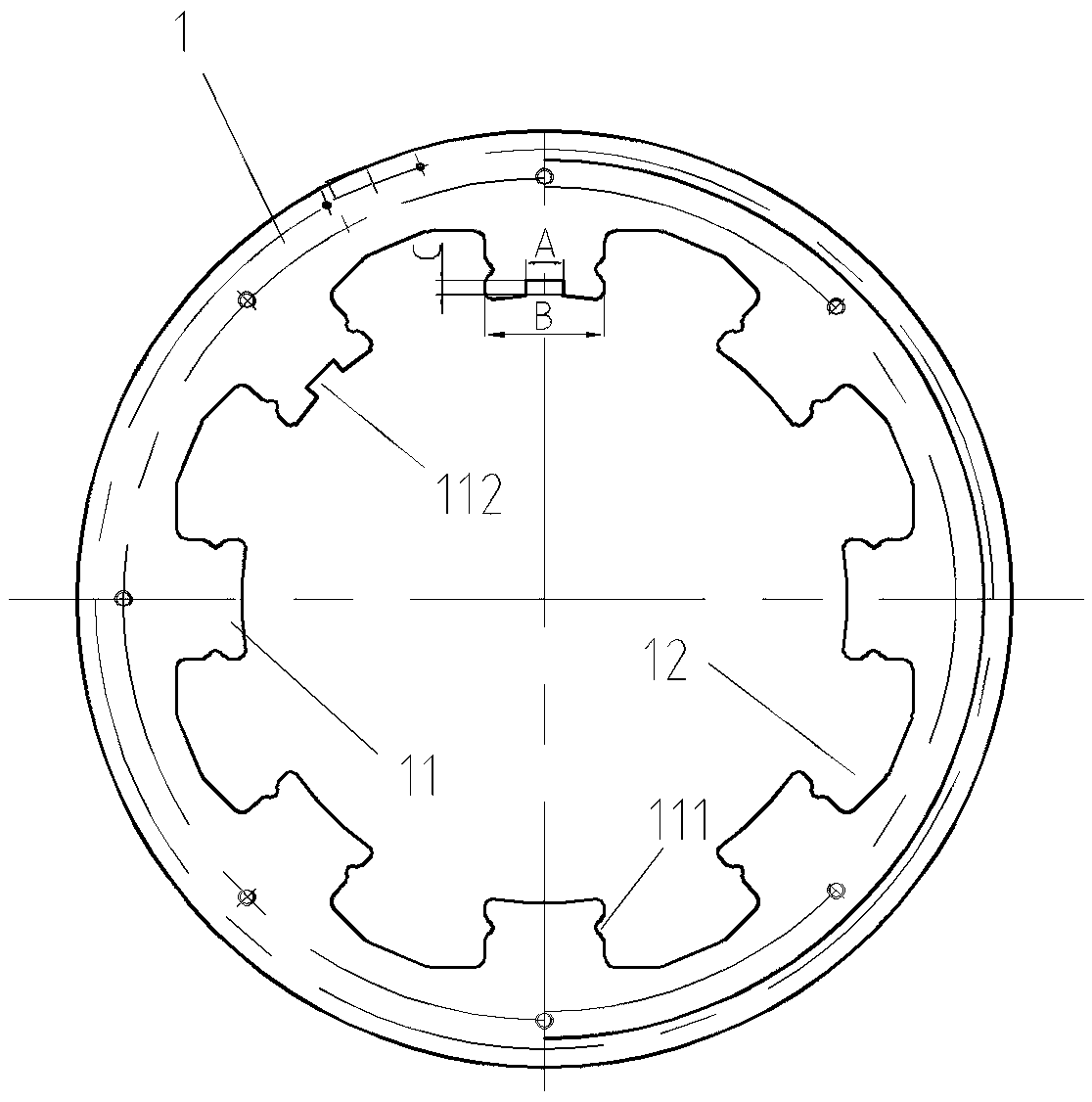
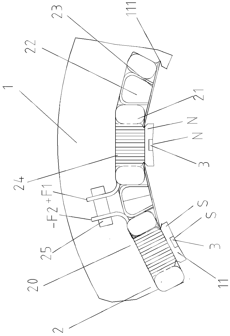
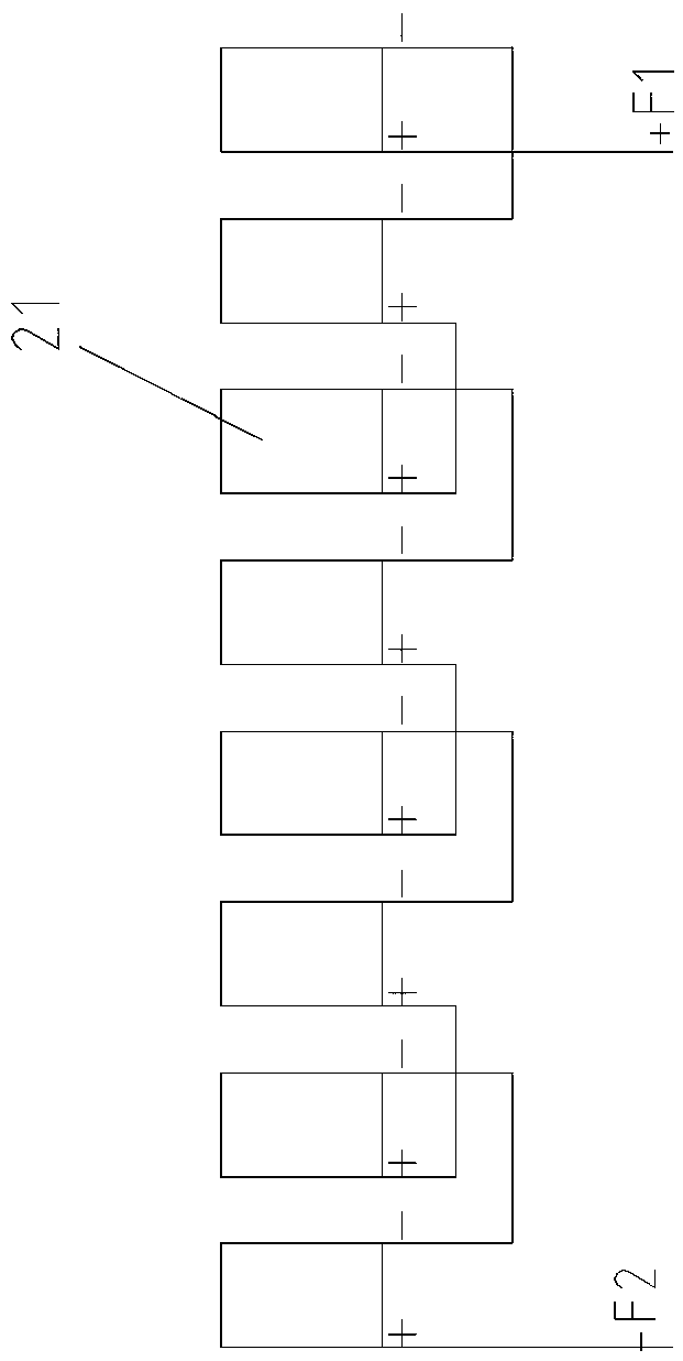
[0035] Such as figure 1 with figure 2 As shown, this embodiment includes a magnetic pole yoke ring 1 and 8 magnetic pole windings 2. The magnetic pole winding 2 includes a coil 21, a slot wedge 22 and a fixing plate 23. The inner holes of the circular magnetic pole yoke ring 1 are evenly distributed with 8 holes facing the pole yoke. The salient poles 11 extending radially from the center of the inner hole of the ring, and the wound coils 21 are respectively sleeved on the salient poles 11 covered with an insulating layer, and the two ends of each coil 21 are respectively connected with adjacent coils 21 to form a coil group 20 . Coils 21 are radially spaced with a plurality of binding bands 24 binding the cross section of the coils. Slot wedges 22 are embedded and fixed between two adjacent coils 2...


PUM


Abstract

The invention discloses a brushless synchronous generator salient pole exciter stator comprising a magnetic pole yoke ring and multiple magnetic pole windings. The wound coils respectively sleeve on salient poles covered with an insulating layer. The two ends of each coil are connected with adjacent coils in turn to form a coil group. The inner holes of coils are respectively abutted on the two side surfaces of the salient poles. A magnetic steel groove is arranged in the centers of the top surfaces of the two adjacent salient poles. A pair of magnetic poles of the magnetic steel are adsorbedand fixed in the magnetic steel groove in an opposite way. The manufacturing method of the stator is as follows: 1) the coils are respectively fixed on multiple salient poles of the magnetic pole yokering; 2) all the coils are connected to form the coil group; 3) two pieces of magnetic steel are arranged in the magnetic steel groove in an opposite way; and 4) the arranged salient pole exciter stator is vacuum-varnished. The reaction speed of the emergency generator is enhanced, the performance of the brushless synchronous generator is improved and the dynamic characteristic of the brushless synchronous generator when the fan load is suddenly added is enhanced and the cost of the brushless synchronous generator is reduced.

Description

technical field [0001] The invention relates to an exciter stator structure of a brushless synchronous generator, in particular to a salient pole type exciter stator and a manufacturing method thereof, belonging to the technical field of motor manufacturing. Background technique [0002] Brushless synchronous generators provide different power and voltage for various equipment loads, and are widely used in the fields of electric power and new energy. It is mainly composed of three parts: the main generator, the exciter and the excitation system. Among them, the main generator is a transition generator, and the exciter is a pivot generator. After the rotor of the exciter rotates, the residual magnetism of the main rotor induces a residual magnetic voltage on the stator. This voltage provides excitation current to the stator of the exciter after passing through the excitation system, and the rotor of the exciter provides an excitation field current to the main rotor through a ...

Claims


Application Information

Patent Timeline
Patent Type & Authority Applications(China)
IPC IPC(8): H02K1/14H02K1/17H02K15/03
CPCH02K1/146H02K1/17H02K15/03
Inventor 朱明赵建华安冠豪曾龙伟
Owner ZHENJIANG ZHONGCHUAN XIANDAI GENERATING EQUIP CO LTD
Learn More