Electromagnetic suspension ball system with acceleration detection function, and control method thereof

An electromagnetic levitation and levitation controller technology, which is applied to controllers with specific characteristics, speed/acceleration/shock measurement, acceleration measurement using inertial force, etc., can solve the vibration, instability, and excessive interference of the electromagnetic levitation ball system To achieve the effect of improving the anti-interference ability, improving the suspension stability and increasing the stability range

Inactive Publication Date: 2019-10-11
SOUTHWEST JIAOTONG UNIV
View PDF6 Cites 9 Cited by
  • Summary
  • Abstract
  • Description
  • Claims
  • Application Information

AI Technical Summary

Problems solved by technology

[0006] However, in practical applications, the differential link has the following disadvantages: (1) The differential control responds too quickly to strong disturbances with fast amplitude changes, while the action speed of the actuator is relatively slow, and cannot respond to the differential control in time. The disturbance cannot be effectively suppressed; (2) If there is a sudden change in the signal entering the differential link, a spike will appear in the output of the controller; (3) The ideal differential control is very sensitive to the noise interference mixed with the deviation signal, which affects the st

Method used


Image

  • Electromagnetic suspension ball system with acceleration detection function, and control method thereof
  • Electromagnetic suspension ball system with acceleration detection function, and control method thereof
  • Electromagnetic suspension ball system with acceleration detection function, and control method thereof

Examples


Embodiment Construction

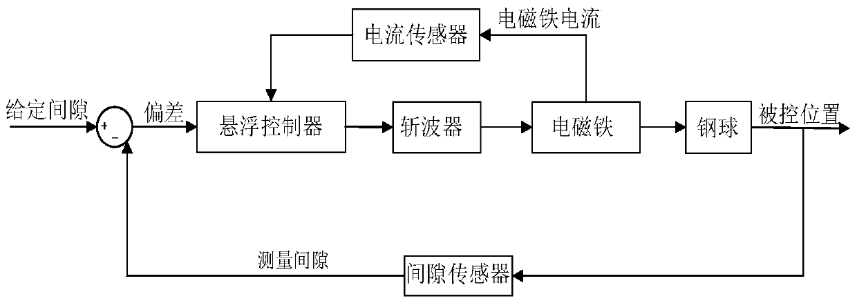
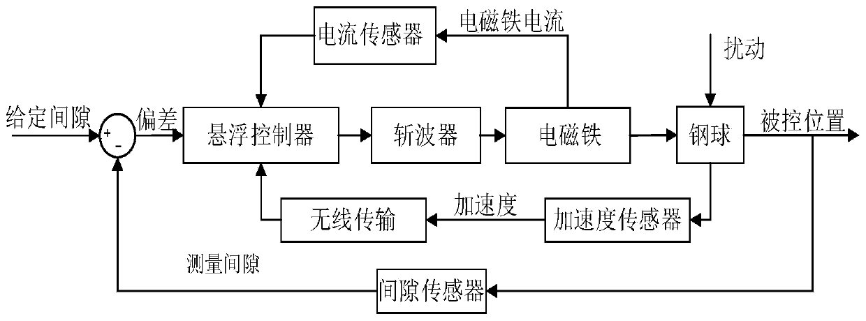
[0038] The present invention will be described in further detail below in conjunction with the accompanying drawings and specific embodiments. The invention designs an electromagnetic levitation ball system with the functions of acceleration detection and wireless transmission, and optimizes the levitation control method in combination with the feedback of acceleration signals. Since the steel ball itself is in a suspended state and has no electrical connection with the outside world in the magnetic levitation ball system, the transmission of the acceleration signal of the steel ball is realized by means of wireless communication. The working principle diagram of the electromagnetic levitation ball system is as follows: figure 2 shown.

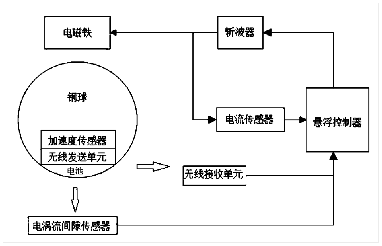
[0039] Such as image 3 As shown, the electromagnetic levitation ball system of the present invention includes an eddy current gap sensor, an acceleration sensor, a levitation controller, a chopper and a current sensor; the eddy current gap...


PUM


Abstract

The invention discloses an electromagnetic suspension ball system with an acceleration detection function, and a control method thereof. In the system, an eddy current gap sensor collects a suspensiongap signal value and sends the same to a suspension controller; an acceleration sensor and a wireless transmitting unit are arranged in a steel ball, the acceleration sensor collects an accelerationvalue of the steel ball and sends the same to a suspension controller through the wireless transmitting unit and a wireless receiving unit; a current sensor detects a current signal of an electromagnet and sends the same to the suspension controller; and the suspension controller determines the magnitude of the current to be output according to the received suspension gap signal value, the acceleration data and real-time of the current signal, and then adjusts the winding current of the electromagnet through a chopper to change the magnitude of an electromagnetic force, so that the steel ballis suspended at a given suspension gap. The electromagnetic suspension ball system disclosed by the invention improves the suspension performance of the suspension system, increases the dynamic stiffness of the system, changes the damping and the vibration frequency of the system, and improves the anti-interference ability and the suspension stability of the system.

Description

technical field [0001] The invention relates to the technical field of electromagnetic levitation, in particular to an electromagnetic levitation ball system with an acceleration detection function and a control method thereof. Background technique [0002] The traditional electromagnetic levitation ball system mainly includes electromagnets, steel balls, gap sensors, levitation control circuits, and choppers. The electromagnetic levitation ball system is a closed-loop control system. Generally, the gap sensor detects the change in the distance between the steel ball and the electromagnet. When the steel ball is disturbed and falls, the distance between the steel ball and the electromagnet increases, and the output voltage of the gap sensor changes. Then The gap voltage signal is sent to the suspension controller for processing, and then the electromagnet current is adjusted through the chopper, so that the electromagnet current increases, the electromagnetic suction increas...

Claims


Application Information

Patent Timeline
IPC IPC(8): G01P15/13G05B11/42G05B13/04
CPCG01P15/132G05B11/42G05B13/042
Inventor 靖永志郝建华孔杰龚倩文张晨昊彭涛廖珍贞钱程张昆仑
Owner SOUTHWEST JIAOTONG UNIV
Why Eureka
Try Eureka