
Waveguide optoelectronic device

A technology for optoelectronic devices and waveguides, applied in the directions of optical waveguides, semiconductor devices, electrical components, etc., it can solve the problem of a large ratio of the height of the waveguide to the thickness of the plate, and achieve the effects of high bandwidth, reduced capacitance, and increased bandwidth.

Pending Publication Date: 2019-10-11
ROCKLEY PHOTONICS INC
View PDF18 Cites 2 Cited by
  • Summary
  • Abstract
  • Description
  • Claims
  • Application Information

AI Technical Summary

Problems solved by technology

However, meeting the slab tolerance requirements of SiGe-based waveguide modulators in large waveguide platforms is challenging in terms of handling and fabrication, especially due to the fact that the ratio of waveguide height to slab thickness is large

Method used


Image

  • Waveguide optoelectronic device
  • Waveguide optoelectronic device
  • Waveguide optoelectronic device

Examples


Embodiment Construction

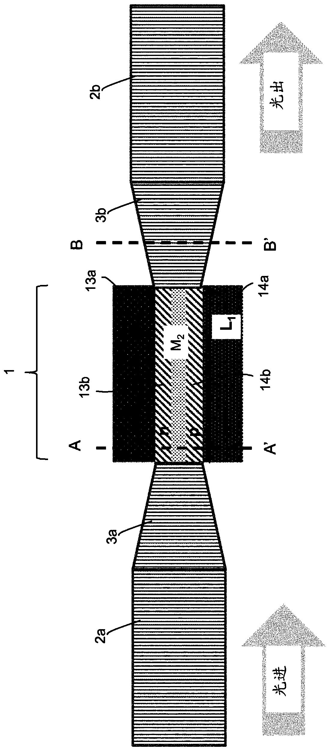
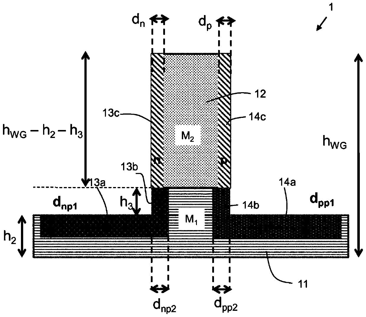
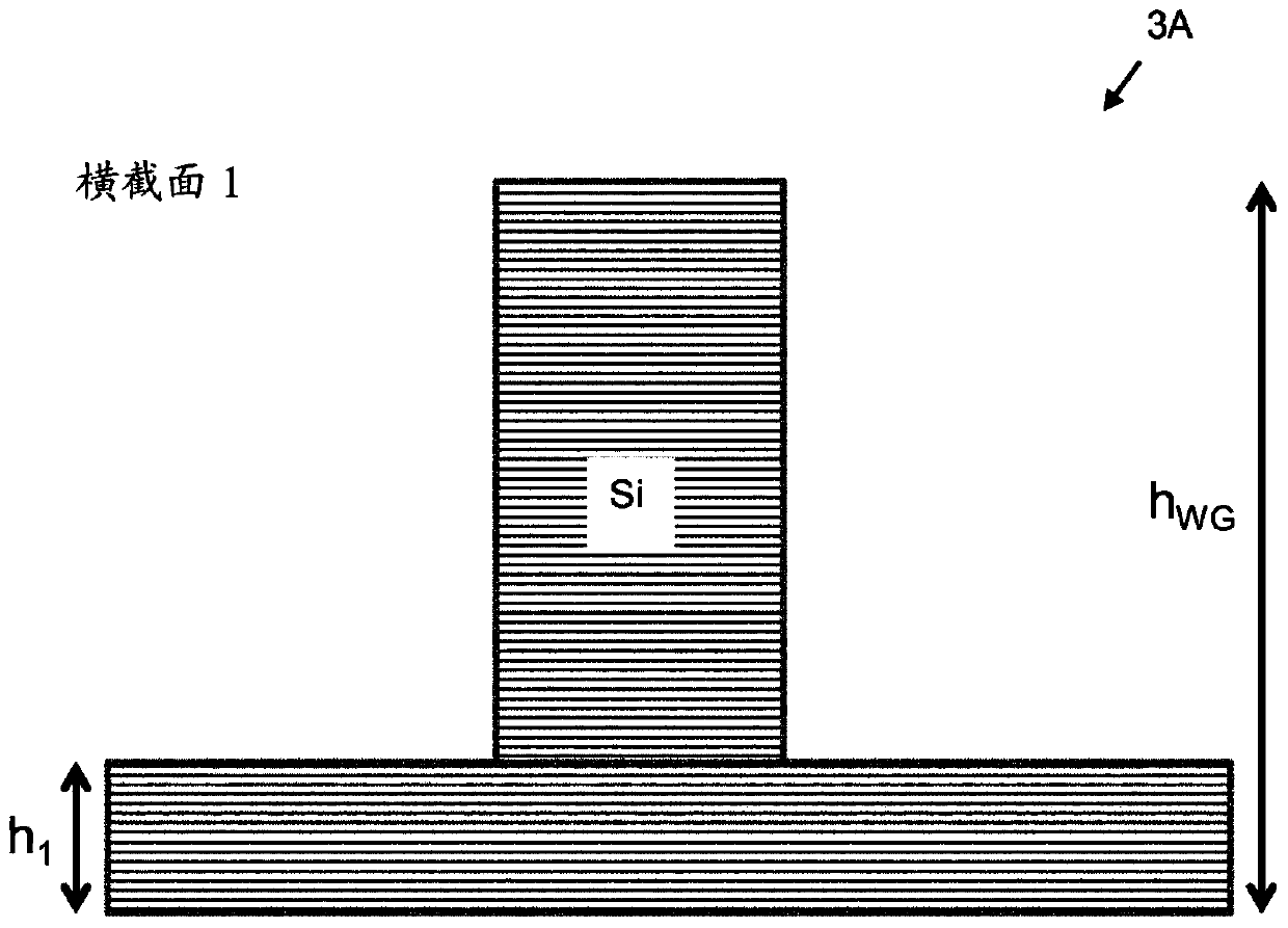
[0064] The detailed description set forth below in conjunction with the accompanying drawings is intended as a description of exemplary embodiments of waveguide optoelectronic devices (EAMs) and / or methods of manufacturing rib-shaped waveguide modulation regions provided in accordance with the present invention, and is not intended to represent that the present invention can be constructed or utilized. only form. This description sets forth the features of the invention in conjunction with the illustrated embodiments. It is to be understood, however, that the same or equivalent functions and structures may be accomplished by different embodiments which are also intended to be encompassed within the spirit and scope of the invention. As indicated elsewhere herein, like element numbers are intended to denote like elements or features. Reference below figure 1 , Figure 2A , Figure 2B , Figure 3A and Figure 3B A waveguide optoelectronic device 1 according to a first embo...


PUM


Abstract

A waveguide optoelectronic device comprising a rib waveguide region, and method of manufacturing a rib waveguide region, the rib waveguide region having: a base of a first material, and a ridge extending from the base, at least a portion of the ridge being formed from a chosen semiconductor material which is different from the material of the base wherein the silicon base includes a first slab region at a first side of the ridge and a second slab region at a second side of the ridge; and wherein: a first doped region extends along: the first slab region and along a first sidewall of the ridge,the first sidewall contacting the first slab region; and a second doped region extends along: the second slab region and along a second sidewall of ridge, the second sidewall contacting the second slab region.

Description

technical field [0001] One or more aspects according to embodiments of the present invention relate to an optoelectronic device, and more particularly, to an optoelectronic device suitable for use with silicon rib waveguides. Background technique [0002] The ability of silicon photonics systems to provide improvements in silicon-based microelectronics has long been recognized. Advances in silicon photonics technology have underpinned the success of such systems, and in particular there is a growing demand for faster and more efficient optical modulators and photodetectors compatible with silicon photonics systems. Electroabsorption modulators (EAMs) comprising SiGe materials have been found to provide state of the art high speed performance because the presence of germanium gives more freedom to optimize the device. However, meeting the slab tolerance requirements of SiGe-based waveguide modulators in large waveguide platforms is challenging in terms of handling and fabric...

Claims


Application Information

Patent Timeline
IPC IPC(8): G02F1/025
CPCG02F1/025G02F2201/063G02F2202/06G02F1/0157G02B6/12G02F1/2257G02F2202/10G02B2006/12097G02B2006/12061G02B2006/12176G02B2006/12178G02B2006/12188H01L31/02327
Inventor H.阿贝戴斯尔D.莱罗塞A.S.纳格拉余国民
Owner ROCKLEY PHOTONICS INC
Learn More