
Fast and efficient hydrocyclone

A hydrocyclone and cyclone technology, which is applied to cyclone devices, devices whose axial directions of cyclones can be reversed, etc., can solve the problems of limited processing capacity, fine underflow and low classification efficiency, etc. Improve separation efficiency, improve processing capacity, and solve the effect of longer residence time

Active Publication Date: 2019-10-15
NORTHEASTERN UNIV
View PDF6 Cites 2 Cited by
  • Summary
  • Abstract
  • Description
  • Claims
  • Application Information

AI Technical Summary

Problems solved by technology

There are many types of existing cyclones. Due to the influence of the structure of the cyclones, most of them have the problems of fine bottom flow, low classification efficiency and limited processing capacity.

Method used


Image

  • Fast and efficient hydrocyclone
  • Fast and efficient hydrocyclone
  • Fast and efficient hydrocyclone

Examples


Embodiment 1

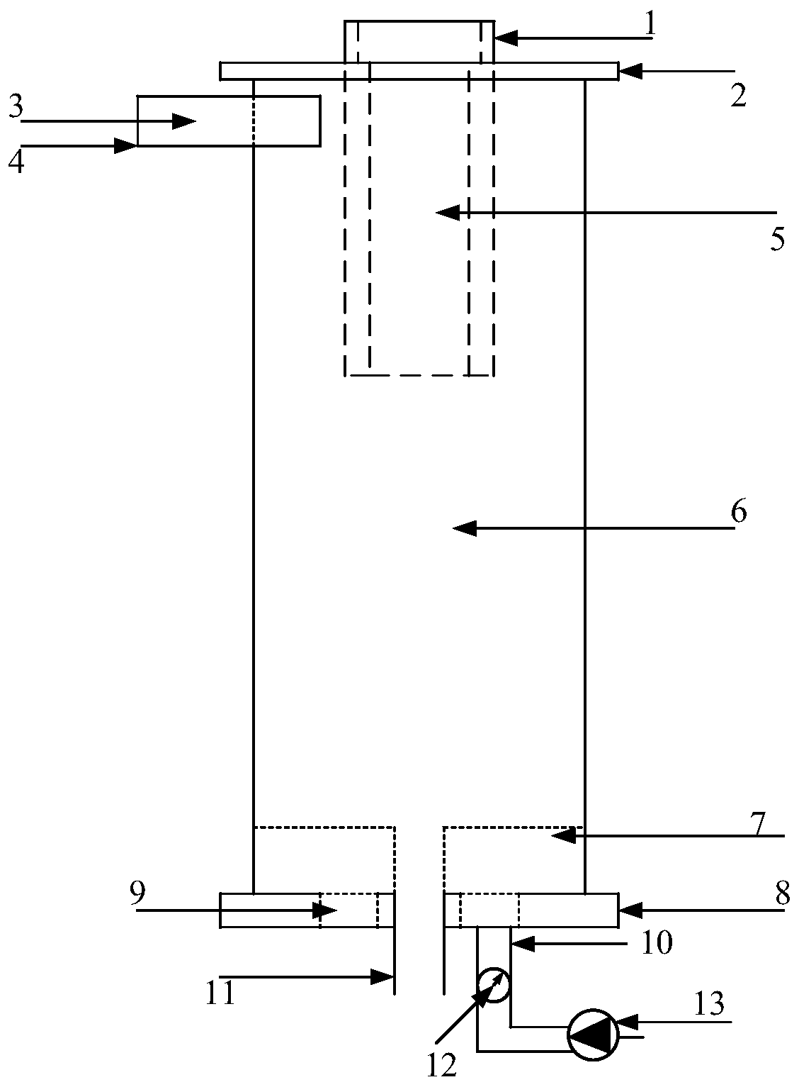
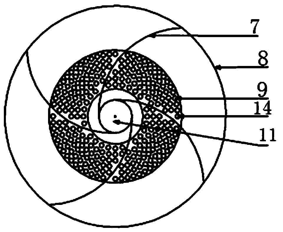
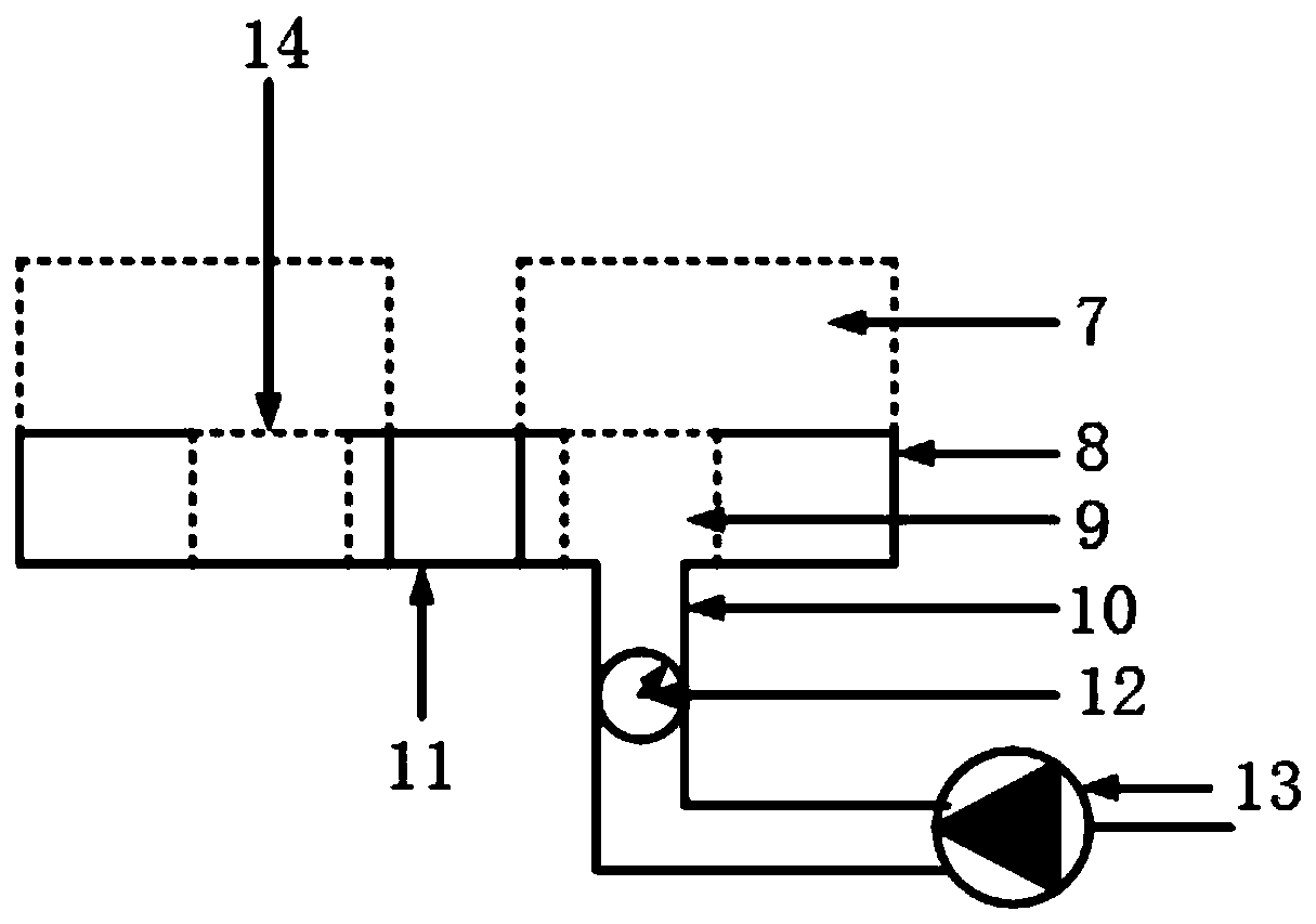
[0033] In this embodiment, a fast and high-efficiency hydrocyclone with a structure of four-divided baffles 7 is adopted, and the baffles 7 are distributed symmetrically in the center, but the number is not limited to four. In this embodiment, the height of the deflector 7 is set to 30mm. The deflector 7 is symmetric about the center of the cylindrical cavity 6 and is tangent to the underflow tube 11. The diameter and pressure of each flushing water outlet 14 are the same. When the particles enter the cyclone Then, the flushing water is fed into the flushing water inlet 10 at a certain pressure, and the flushing water is discharged from the flushing water outlet 14 at a certain speed. According to the theory of fluidization, under the action of flushing water, when the axial velocity of the flushing water is greater than the initial fluidization velocity (Umf), the particles entering the bottom of the cyclone are loose and floating, forming fluidization. When the flow velocity ...

Embodiment 2

[0035] The difference between this embodiment and embodiment 1 is that the height of the deflector 7 in this embodiment is set to 45mm, and the deflector 7 is centrally symmetric about the center of the cylindrical cavity 6 and is tangent to the underflow tube 11, so that the system runs stably. After that, the increase in calculation processing amount and the increase in classification efficiency are recorded.

Embodiment 3

[0037] The difference between this embodiment and embodiment 1 is that the height of the deflector 7 in this embodiment is set to 60mm, and the deflector 7 is symmetric about the center of the cylindrical cavity 6 and is tangent to the underflow tube 11, so that the system is stable. After that, the increase in calculation processing amount and the increase in classification efficiency are recorded.


PUM


Abstract

The invention belongs to the technical field of material separation, and discloses a fast and efficient hydrocyclone. The hydrocyclone comprises a hydrocyclone body, and further comprises a flushing water distributor and flow guide plates, the flushing water distributor and the flow guide plate are connected with a bottom cover on the hydrocyclone body through a welding mode, and the flow guide plates are in central symmetry with respect to the center of a cylindrical cavity on the hydrocyclone body and is tangent to a underflow pipe on the hydrocyclone body. Materials are fed from a feeding port and spirally move in the hydrocyclone, when the particles move to the bottom of the hydrocyclone, fine particles are brought out to enter an inner rotational flow under the action of upward flushing water, and meanwhile, under the action of the flow guide plates, separated coarse particles are rapidly guided to an underflow port to be discharged on the basis of the original rotation motion. According to the hydrocyclone, the effect of the internal flow field of the hydrocyclone is strengthened by utilizing a fluidization principle, and the amount of the fine particles in an underflow is reduced, so that the separation efficiency of the wide-grade materials is greatly improved; and meanwhile, the residence time of the coarse particles is reduced, and the treatment capacity of the hydrocyclone is further improved.

Description

Technical field [0001] The invention relates to the technical field of material separation, in particular, to a fast and efficient hydrocyclone. Background technique [0002] As one of the important equipment in the field of material separation in industry, the hydrocyclone uses the principle of centrifugal sedimentation to achieve material separation. The material enters the cyclone from the inlet under a certain pressure and produces a strong rotational movement. Under the action of centrifugal force, the coarse and heavy particles move outwards into the outer cyclone and are discharged from the grit port; under the action of fluid drag and centripetal buoyancy , The fine and light particles migrate inward and enter the internal swirling flow to be discharged from the overflow port, thus completing the separation and classification of the particles. Its simple structure, high separation efficiency, simple operation, small footprint, and a wide range of industrial applications,...

Claims


Application Information

Patent Timeline
Patent Type & Authority Applications(China)
IPC IPC(8): B04C5/00B04C5/14
CPCB04C5/00B04C5/14
Inventor 崔宝玉侯端旭赵强魏德洲张浩孟令国王学涛
Owner NORTHEASTERN UNIV
Learn More