
An open mim waveguide structure

A waveguide structure and open-type technology, applied in the field of open-type MIM waveguide structure, can solve problems such as Q factor instability, and achieve the effects of Q factor stability, Q factor improvement, and high sensitivity

Active Publication Date: 2021-02-12
山东昊盾警用装备有限公司
View PDF21 Cites 0 Cited by
  • Summary
  • Abstract
  • Description
  • Claims
  • Application Information

AI Technical Summary

Problems solved by technology

[0005] In view of the above problems, the purpose of the present invention is to solve the problem of unstable Q factor that exists when the optical waveguide device of the existing guided wave optical system performs waveguide coupling.

Method used


Image

  • An open mim waveguide structure
  • An open mim waveguide structure
  • An open mim waveguide structure

Examples


Embodiment 1

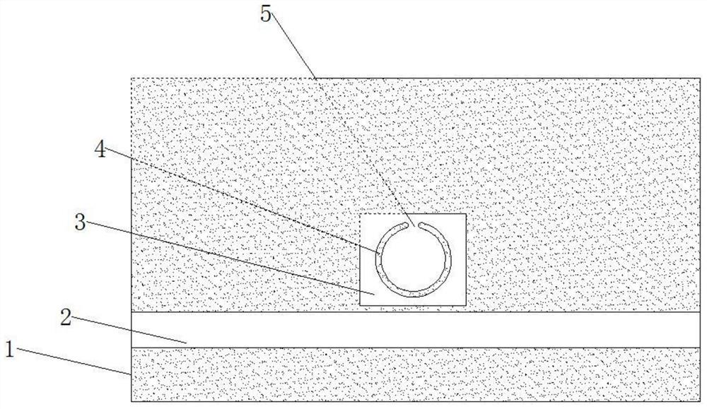
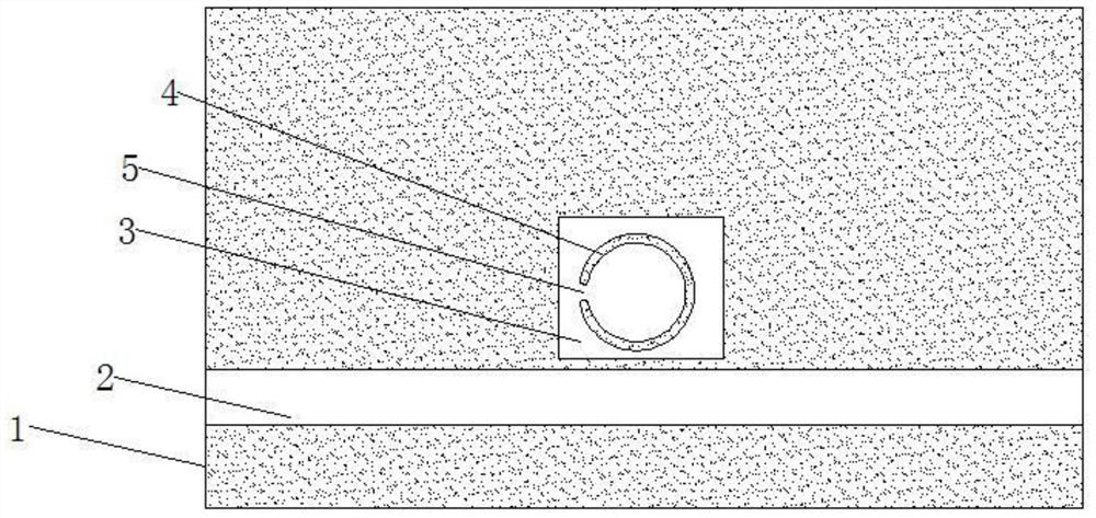
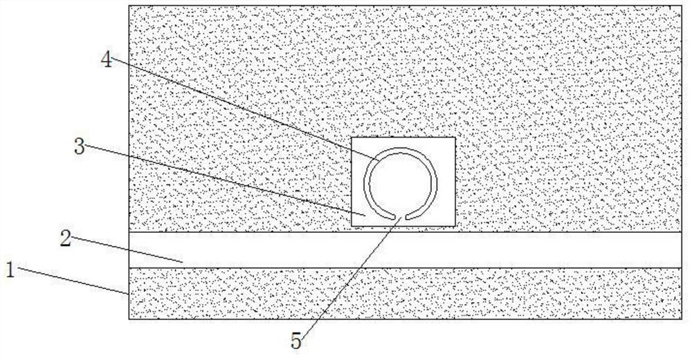
[0028] In order to solve the defect that the Q factor is unstable when the optical waveguide device of the existing waveguide optical system performs waveguide coupling. This embodiment provides a Figure 1 ~ Figure 3 The shown open-type MIM waveguide structure includes a main body 1, an optical channel 2 is arranged above the main body 1; a resonant cavity 3 is arranged above the optical channel 2; a resonant ring 4 is arranged in the resonant cavity 3; The resonant ring 4 is provided with an opening 5; when the light enters the optical channel 2 from the entrance at the left end, surface plasmons will be excited in the optical channel 2, and are coupled with the upper resonant cavity 3 and the resonant ring 4 , the resonant cavity 3 and the resonant ring 4 each generate different plasmon resonances, and the different plasmon resonances combine to form a hybrid plasmon resonance, so that the MIM waveguide structure has a high Q factor, and The MIM waveguide structure has the...


PUM

PropertyMeasurementUnit
diameteraaaaaaaaaa

Abstract

The invention relates to an open-type MIM (metal-medium-metal) waveguide structure, comprising a main body, an optical channel is arranged above the main body; a resonant cavity is arranged above the optical channel; a resonant ring is arranged in the resonant cavity ; The resonant ring is provided with an opening; the open-type MIM waveguide structure has the advantages of small size, easy integration, and high sensitivity. By setting a square ring in the main body and an open ring inside the square ring, different The plasmon resonance of the hybrid form forms a hybrid plasmon resonance, and the resulting resonance type is relatively stable, thereby improving the Q factor of the waveguide and making the Q factor of the waveguide more stable. In addition, due to the open ring As a result, the plasmon resonance propagating on the ring is cut off, forming a standing wave mode, which couples with the long waveguide to form a narrower transmission peak. When this structure is used to make a sensor, the refractive index of the medium at the gap will seriously affect the resonance mode, thereby realizing a sensor with higher sensitivity.

Description

technical field [0001] The invention belongs to the technical field of waveguide structures, and in particular relates to an open MIM waveguide structure. Background technique [0002] Based on the electromagnetic theory of light, guided wave optics studies the effects of propagation, scattering, polarization, and diffraction of light waves in optical waveguides, and has become the theoretical basis for various optical waveguide devices and fiber optic technologies. Usually people divide the research of optical fiber and other guided wave optics into two different fields, namely fiber optics and integrated optics, but their theoretical basis is the same, which is guided wave optics. [0003] A guided wave optical system generally consists of a light source, a coupler, an optical waveguide device, an optical modulator, and an optical detector. Compared with traditional, non-integrated discrete optical component systems, guided wave optical systems have the characteristics of...

Claims


Application Information

Patent Timeline
Patent Type & Authority Patents(China)
IPC IPC(8): G02B6/00
CPCG02B6/00
Inventor 李道勇张中侠
Owner 山东昊盾警用装备有限公司
Learn More