Energy-saving environment-protecting material sucking and drying all-in-one machine

An energy-saving and environmentally-friendly integrated machine technology, applied in the field of injection molding, can solve the problems of high investment and production costs, easy blockage of feeding equipment, and large space occupation, and achieve fast drying speed, remarkable energy-saving effect of equipment, and slow fan speed.

Active Publication Date: 2019-10-18
温州市鸿燊自动化有限公司
View PDF4 Cites 3 Cited by
  • Summary
  • Abstract
  • Description
  • Claims
  • Application Information

AI Technical Summary

Problems solved by technology

[0004] The purpose of the present invention is: in order to solve the problems of needing to purchase drying equipment and feeding equipment, occupying a large space, high investment and production costs, large energy consumption, large dust, and easy blockage of feeding equipment, an automated production method is proposed. Energy saving and environmental protection suction and dry material all-in-one machine

Method used


Image

  • Energy-saving environment-protecting material sucking and drying all-in-one machine
  • Energy-saving environment-protecting material sucking and drying all-in-one machine
  • Energy-saving environment-protecting material sucking and drying all-in-one machine

Examples


Embodiment 1

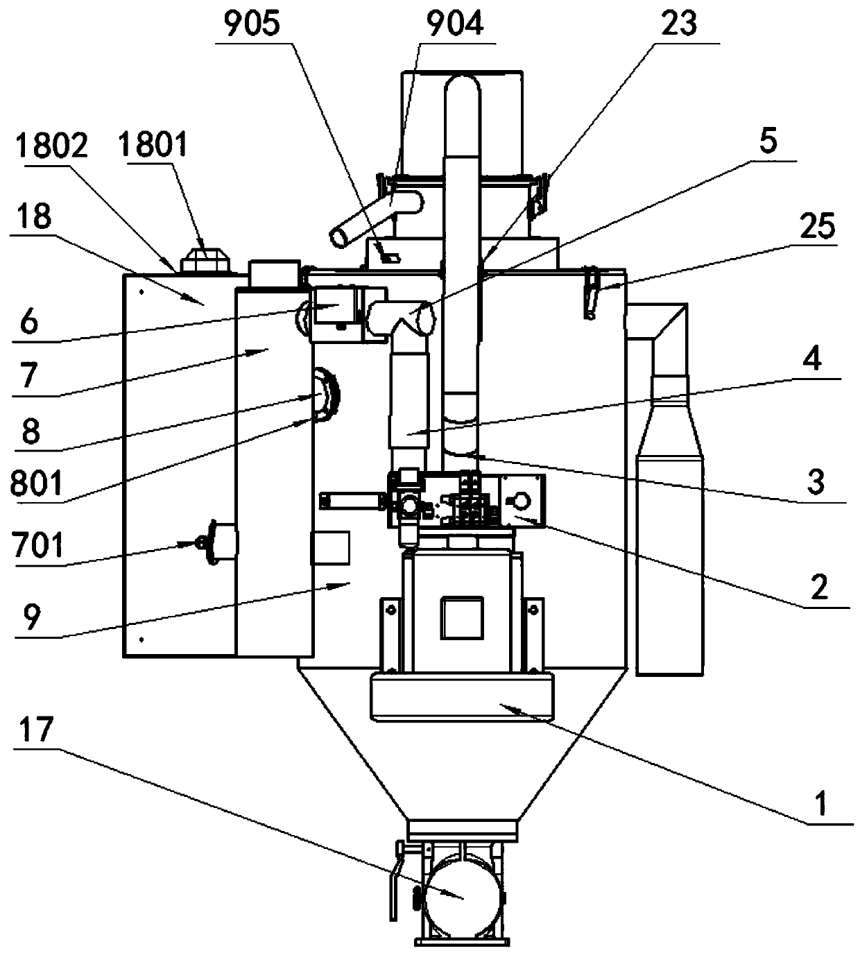
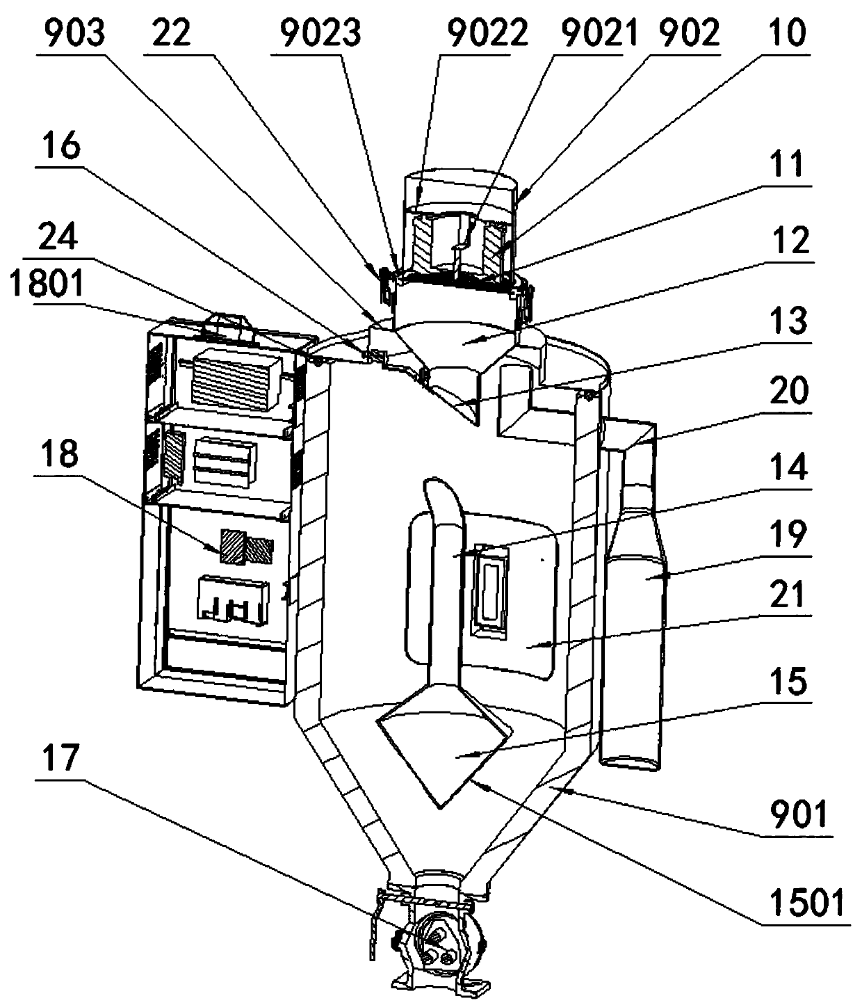
[0055] 4. See Figure 1 to Figure 4 , an energy-saving and environmentally friendly suction and dry material integrated machine, comprising a barrel main body (9), a fan (1), a pulse switching exhaust mechanism (2), a heater (7), a feeding device (17), and a barrel main body The electrical control system (18) installed on the outer side and components such as connecting pipe fittings are formed. The barrel main body (9) is divided into four parts: the main body shell (901), the hopper top cover (902), the material hopper (12), and the barrel upper cover (903). The main body shell (901) has a double-layer stainless steel structure. A fan (1) is fixedly connected to the lower part of the cylindrical side wall, and the two vents on the top of the fan (1) are connected with a pulsating switching exhaust device (2), and the upper end surface of the pulsating switching exhaust device (2) is respectively connected with a The first air duct (3) and the second air duct (4), the upper ...

Embodiment 2

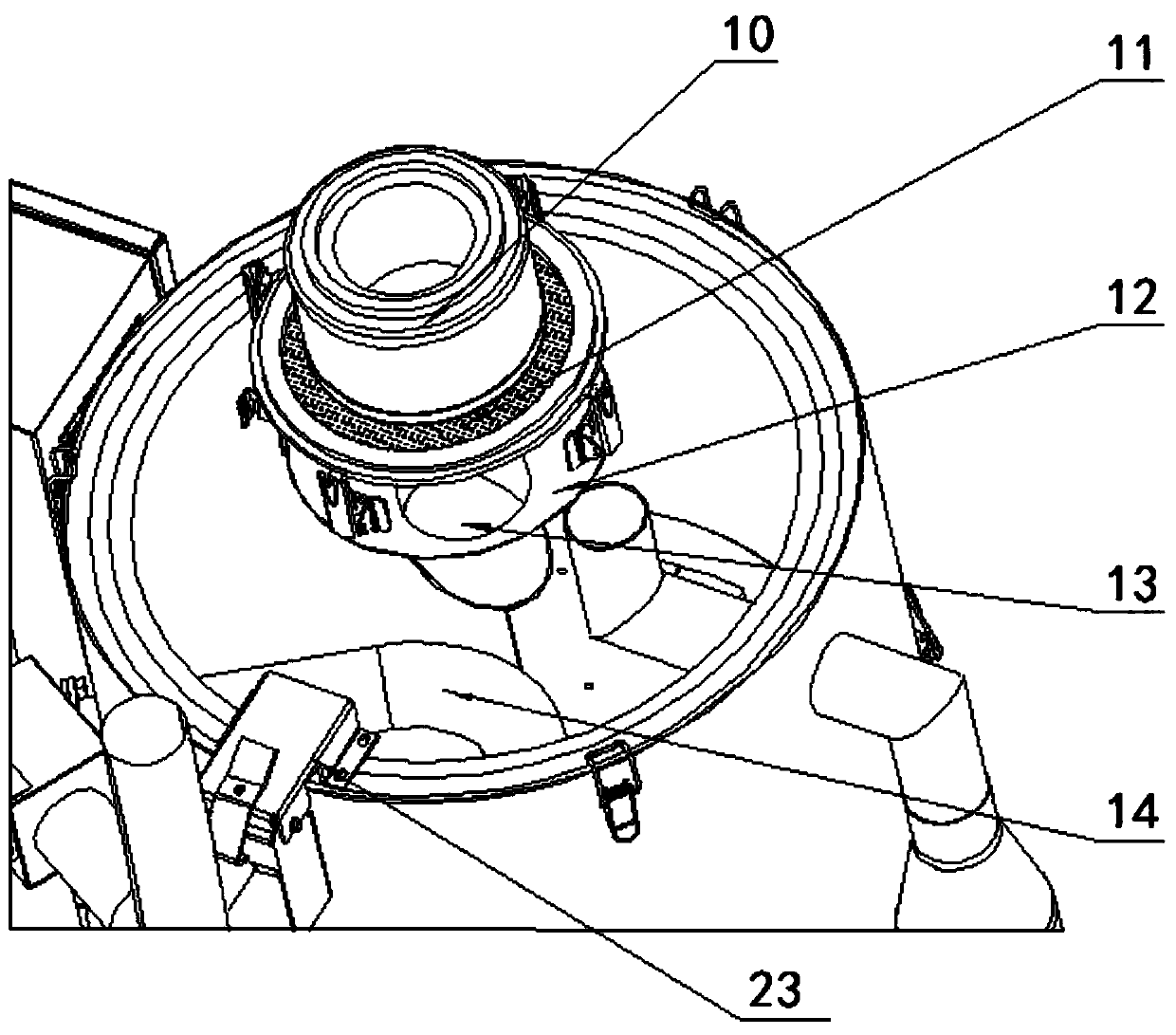
[0057] see image 3 and 4 , the hopper top cover (902) is connected with the material hopper (12) through the top cover buckle (22), and the mating surface is sealed by a coarse filter sealing ring (9023) fixed with a stainless steel coarse filter (11), and the hopper top cover (902) is horizontally welded with a ring plate (9022) close to the upper inner wall, and the ring plate (9022) is welded with a fine filter holder (9021) for fixing the filter paper fine filter screen (10), and the ring plate (9022 ) lower end surface is sealed with a filter paper fine filter screen (10) with a cylindrical structure through the fine filter fixing frame (9021), so that the material will not flow from the top cover of the hopper under the action of the stainless steel coarse filter screen 11 and the filter paper fine screen screen 10. flow out. At the same time, the main body shell (901) is fixedly connected with the barrel upper cover (903) through the upper cover buckle (25), and the ...

Embodiment 3

[0059] see figure 1 and 3 A return air temperature and humidity detection sensor (905) and a material level detection switch (16) are arranged on the cylindrical side wall of the barrel upper cover (903) close to the feed pipe (904), and the lower end of the material hopper (12) is attached to the inclined surface There is a material baffle (13), and the material baffle (13) is connected to the output end of the material level detection switch (16). (14) Through the main body casing (901) and communicate with the fourth air pipe (8), and the lower end surface of the fifth air pipe (14) communicates with a heat dissipation conical pipe (15), on the heat dissipation tapered pipe (15) There are a plurality of conical tube microholes (1501) penetrating through the side surface wall of the heat dissipation conical tube (15), so that the material level detection switch 16 controls the material baffle plate 13 to control the material, so as to facilitate the discharge of the materia...


PUM


Abstract

The invention discloses an energy-saving environment-protecting material sucking and drying all-in-one machine. The machine is composited of a material barrel main body, a fan, a pulsation switching exhaust mechanism, a heater, an electrical control system, a connecting pipe fitting and other components. According to the material sucking and drying all-in-one machine, an air cylinder of the pulsation switching exhaust mechanism is controlled to act through the electrical control system, so that the circulating process such as internal vacuum material sucking and feeding, air flow heating and drying the materials, hot air recycling through filtering and refluxing, and dust filtering, cleaning, bag collecting in materials in the material barrel are carried out; in the process, the electricalcontrol system receives and processes signals feedback from sensor switch such as air pressure, temperature and material level, so that the intelligent control of the drying air volume and the heating temperature in the material processing process is realized, and the energy-saving effect is remarkable; according to the material sucking and drying all-in-one machine, a blanking device adopts a rotary disc sealing type blanking structure, so that the sealing effect is good, and the operation is convenient; and metal impurities in the materials can be effectively adsorbed by the arrangement ofa magnetic column, the metal impurities can be timely removed through a cleaning window, so that the injection molding quality of products is ensured, and the use safety of an injection molding machine is ensured.

Description

technical field [0001] The invention relates to the technical field of injection molding, in particular to an energy-saving and environment-friendly material suction and dry material integrated machine. Background technique [0002] Injection molding is a method of producing industrial products. Products usually use rubber injection molding and plastic injection molding. Injection molding can also be divided into injection molding molding method and die-casting method. Injection molding machine uses plastic molding molds to make thermoplastic particles into various shapes. The main molding equipment for plastic products, injection molding is achieved through injection molding machines and molds. [0003] During the feeding process of rubber and plastic granules, it is generally necessary to fill the drying equipment with materials through the feeder first and then pre-dry them. After the moisture content of the dried materials reaches the standard, the drying machine is used...

Claims


Application Information

Patent Timeline
Patent Type & Authority Applications(China)
IPC IPC(8): B29C45/18B29B13/06B29B13/10B29C45/76
CPCB29B13/10B29C45/18B29C45/76B29C2045/0096
Inventor 卢显龙
Owner 温州市鸿燊自动化有限公司
Why Eureka
Try Eureka