Concrete shallow-surface-layer ultrasonic surface wave detection method based on arrangement type ultrasonic seismic focus

A detection method and array technology, which is applied to the analysis of solids using sound waves/ultrasonic waves/infrasonic waves, material analysis using sound waves/ultrasonic waves/infrasonic waves, and measuring devices. It can only achieve meter-level, low precision, and no traffic Noise and other problems can be achieved to reduce costs, improve detection accuracy, and reduce detection costs

Active Publication Date: 2019-10-18
四川幔壳科技有限公司
View PDF10 Cites 6 Cited by
  • Summary
  • Abstract
  • Description
  • Claims
  • Application Information

AI Technical Summary

Problems solved by technology

[0005] The conventional detection method drag chain method has two shortcomings. On the one hand, it is severely restricted by the external environment and cannot detect reinforced concrete structures with asphalt coverings; The area to be tested; strict traffic control is required during detection, and no traffic noise is allowed; on the other hand, due to the size of the chain itself and the limitation of acoustic feedback sensitivity, the accuracy is relatively low and can only reach the meter level, and the judgment standard is too subjective. Determined by technicians based on experience, resulting in poor stability of results

Method used


Image

  • Concrete shallow-surface-layer ultrasonic surface wave detection method based on arrangement type ultrasonic seismic focus
  • Concrete shallow-surface-layer ultrasonic surface wave detection method based on arrangement type ultrasonic seismic focus
  • Concrete shallow-surface-layer ultrasonic surface wave detection method based on arrangement type ultrasonic seismic focus

Examples


Embodiment Construction

[0048] The technical solution of the present invention will be further described in detail below in conjunction with the accompanying drawings, but the protection scope of the present invention is not limited to the following description.

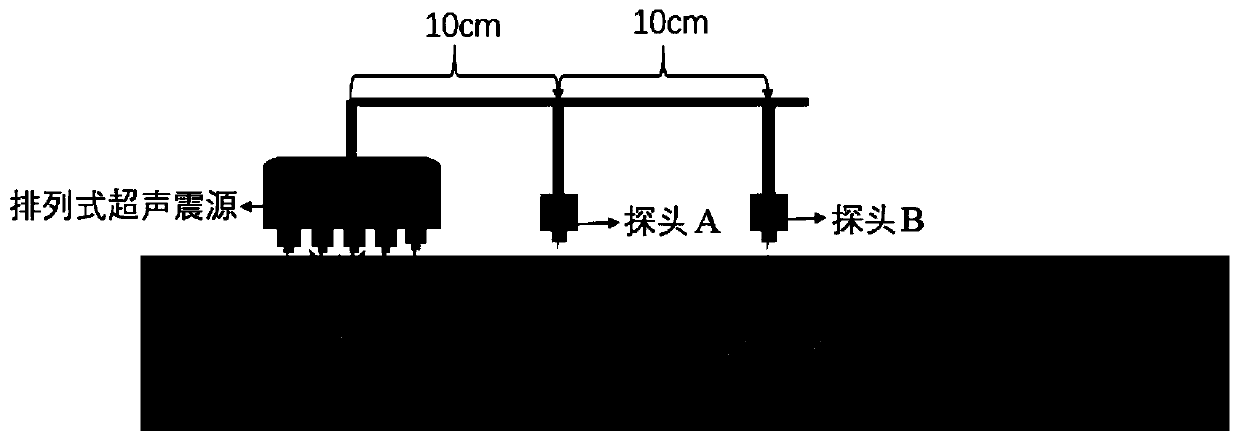
[0049] Such as Figure 5 As shown, the superficial ultrasonic surface wave detection method of concrete based on the arrayed ultrasonic source is realized by the source device and the receiver device;

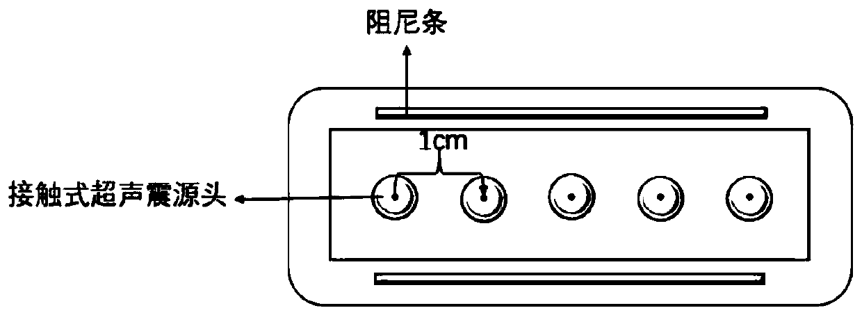
[0050] The source device includes a contact ultrasonic probe, which is in direct contact with the surface of the measured object during detection;

[0051] The receiving device includes two ultrasonic receiving probes: probe A and probe B, and the distances between probe A and probe B and the source are respectively Xcm and Ycm (such as figure 2 shown);

[0052] The whole detection method includes three stages of data acquisition, data processing and shallow surface shear wave velocity calculation:

[0053] data collection:

[0054]Befo...


PUM


Abstract

The invention discloses a concrete shallow-surface-layer ultrasonic surface wave detection method based on an arrangement type ultrasonic seismic focus. The concrete shallow-surface-layer ultrasonic surface wave detection method is implemented by a seismic focus device and a receiving device and comprises three stages of data acquisition, data processing and shallow surface layer shear wave velocity calculation; in the data acquisition stage, before data acquisition is started, firstly, a detection region needs to be determined, region meshing is carried out on a to-be-detected surface according to a detection level resolution demand, and all scanning point positions are determined, then scanning is sequentially carried out on each point position, and the process is repeated until scanningon all the point positions is finished; the data processing comprises signal coherence analysis, phase extraction and average surface wave velocity calculation; and according to a data processing result, shallow surface layer shear wave velocity calculation is carried out so as to judge whether a shallow surface layer below the detection region has defects. According to the invention, a surface wave phase velocity is extracted by phase analysis and an average shear wave velocity of a shallow surface layer of concrete is estimated hereby; and on the basis of a corresponding relationship between the shear wave velocity and medium hardness, a defect region of the shallow surface layer of the concrete is detected and identified.

Description

technical field [0001] The invention relates to an ultrasonic surface wave detection method of concrete shallow surface layer based on arrayed ultrasonic vibration sources. Background technique [0002] With the continuous and stable development of my country's economy, the country is increasingly strengthening infrastructure construction. High-speed (passenger dedicated line) / heavy-haul railways and expressways are the main directions for the development of railways, roads and land transportation respectively. The level of new railways and road tunnels , scale and quantity are increasing year by year. In tunnel engineering, concrete is one of the main structural materials of buildings. Concrete is a multiphase composite system, and the phases are randomly intertwined to form an extremely complex internal structure. The damage of concrete is inevitable, including physical Processes, such as freeze-thaw cycles, fire, water erosion, and chemical processes, such as carbonizatio...

Claims


Application Information

Patent Timeline
Patent Type & Authority Applications(China)
IPC IPC(8): G01N29/07G01N29/44
CPCG01N29/07G01N29/4436G01N29/449
Inventor 陈曦微郑懿马飞鸿梁居祥
Owner 四川幔壳科技有限公司
Why Eureka
Try Eureka