Distributed radar imaging method for resource optimum allocation

A technology for radar imaging and resource optimization, applied in measurement devices, radio wave reflection/re-radiation, and re-radiation, can solve the problems of off-grid targets, rapid imaging performance degradation, and inability to obtain effective information. Resolving imaging, increasing the effect of transmitting signal bandwidth

Active Publication Date: 2019-10-18
UNIV OF ELECTRONICS SCI & TECH OF CHINA
View PDF10 Cites 9 Cited by
  • Summary
  • Abstract
  • Description
  • Claims
  • Application Information

AI Technical Summary

Problems solved by technology

In the document "Xingbin Han, XiaoyongDu, Weidong Hu, and Wenxian Yu, The imaging principle and method based on distributed multi-channel radars [C]. CIE International Conference on Radar, 2006, pp.696–700.", the author uses the inverse fast The Fourier transform (IFFT) method realizes the imaging of wavenumber domain data, and the number of channels for transmitting and receiving radar is large. When the number of sending and receiving is gradually reduced, the imaging perf...

Method used


Image

  • Distributed radar imaging method for resource optimum allocation
  • Distributed radar imaging method for resource optimum allocation
  • Distributed radar imaging method for resource optimum allocation

Examples


Embodiment Construction

[0046] In the present invention, each step has been simulated on the MATLAB R2018a platform.

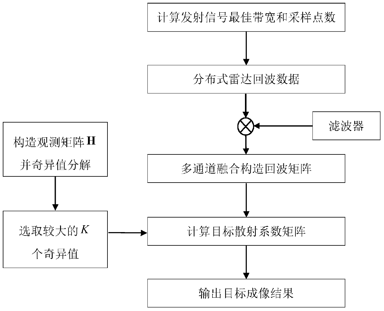
[0047] Such as figure 1 Shown is the flow chart of the method of the present invention, a distributed radar imaging method for resource optimization configuration of the present invention, by calculating the optimal transmission signal bandwidth and the optimal number of sampling points, and constructing the echo matrix according to the optimal bandwidth and the number of sampling points and the observation matrix, so as to calculate the target scattering coefficient matrix, and realize the inversion of the target in the scene according to the target scattering coefficient matrix.

[0048] Specifically include the following steps:

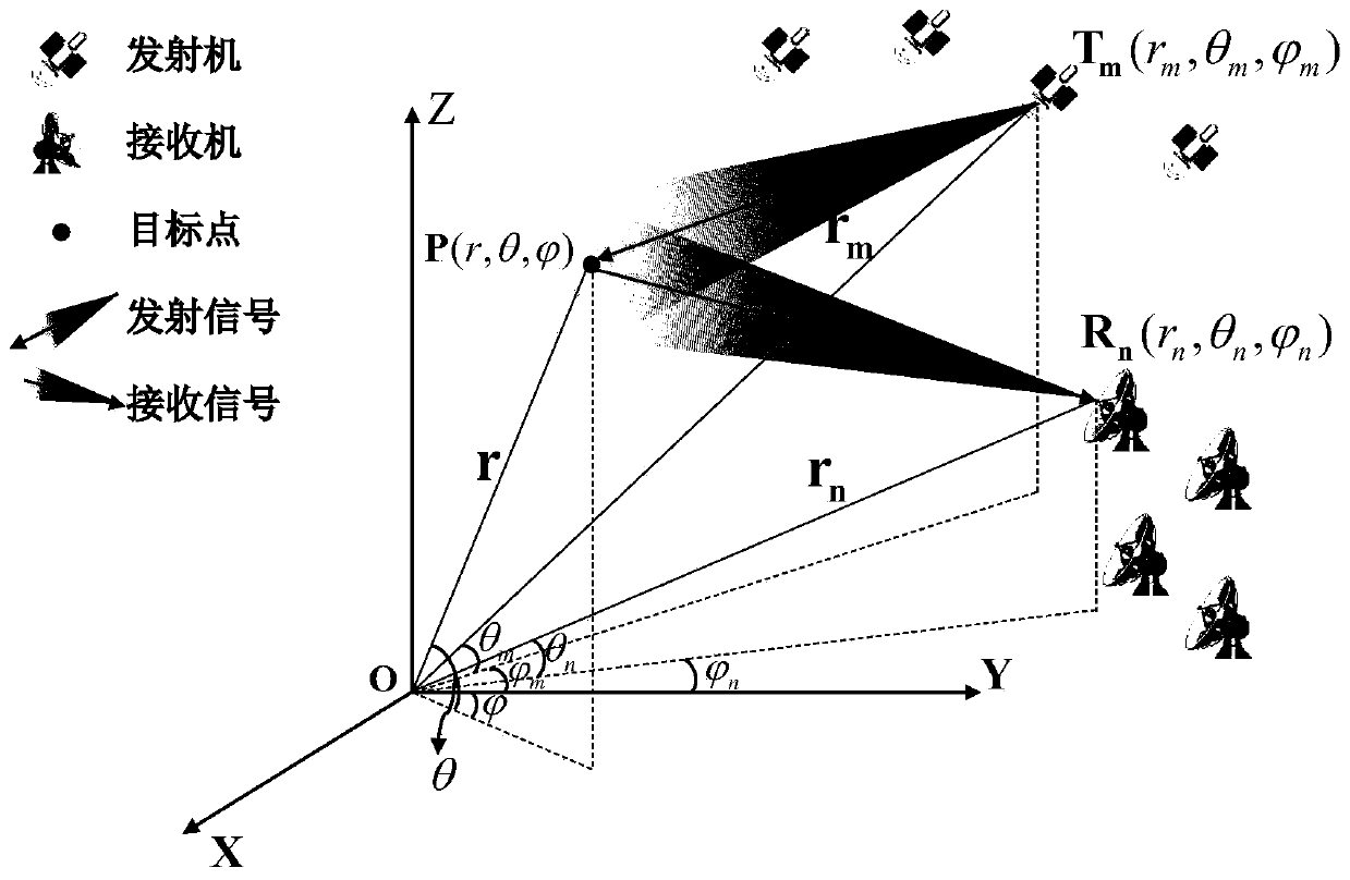
[0049]S1. Determine the distributed radar imaging geometric model and the spatial spectrum signal model;

[0050] S2. Determine the optimal transmit signal bandwidth and the number of system sampling points based on the spatial spectrum signal model;

...


PUM


Abstract

The invention discloses a distributed radar imaging method for resource optimum allocation. The method is applied to the field of radar imaging detection. For the high resolution imaging problem generated when resources of a transmitter and a receiver are limited, according to the method provided by the invention, through analysis of a distributed radar wave number domain spatial spectrum rule, adistributed radar imaging geometric model and a spatial spectrum signal model are exported; through analysis of singular value distribution of a measurement matrix, influences of signal transmitting bandwidths and the number of radar receiving channels on spatial spectrum are determined, so the optimum signal transmitting bandwidth and the optimum radar transmitting and receiving number are obtained; and system echo and system observation matrixes are regenerated based on the optimum signal transmitting bandwidth and the optimum radar transmitting and receiving number, and distributed radar imaging is realized through utilization of a truncated singular value decomposition algorithm. According to the method provided by the invention, through reduction of the radar transmitting and receiving number, the system signal transmitting bandwidth is improved, and distributed radar imaging resolution is improved.

Description

technical field [0001] The invention belongs to the field of radar imaging detection, in particular to a distributed radar imaging technology. Background technique [0002] Radar uses the reflection of electromagnetic waves to realize the detection, positioning, tracking and identification of targets. Compared with optical imaging, it can image the target all-weather and all-weather, and is not affected by weather, shelters, etc. It plays an important role in long-distance target tracking, natural disaster detection and other civil and military fields. [0003] Compared with synthetic aperture radar (SAR) which uses relative motion to achieve a larger aperture, distributed radar imaging can use the spatial diversity relationship between the transmitter and receiver to form a larger observation aperture. In the document "Xingbin Han, XiaoyongDu, Weidong Hu, and Wenxian Yu, The imaging principle and method based on distributed multi-channel radars [C]. CIE International Confe...

Claims


Application Information

Patent Timeline
IPC IPC(8): G01S13/89G01S7/42G01S7/41G01S7/292G01S7/35
CPCG01S7/2923G01S7/354G01S7/41G01S7/42G01S13/89
Inventor 黄钰林徐帆云张永伟张永超张寅裴季方杨建宇
Owner UNIV OF ELECTRONICS SCI & TECH OF CHINA
Why Eureka
Try Eureka