A Photon Counting Imaging Detector

An imaging detector and photon counting technology, applied in the direction of instruments, etc., can solve the problems of slow time response, inability to provide photon arrival time information, affecting the signal-to-noise ratio of charge signal measurement and time response speed, etc.

Active Publication Date: 2020-10-13
CHANGCHUN INST OF OPTICS FINE MECHANICS & PHYSICS CHINESE ACAD OF SCI
View PDF9 Cites 0 Cited by
  • Summary
  • Abstract
  • Description
  • Claims
  • Application Information

AI Technical Summary

Problems solved by technology

The disadvantage of the charge signal encoding anode is that the impedance and capacitive reactance are large, which affects the measurement signal-to-noise ratio and time response speed of the charge signal, resulting in low spatial resolution and count rate of the imaging detector, and the imaging performance is not ideal.
The photon counting imaging detector based on the arrival time encoding anode can decode the spatial position of the photon by measuring the time when the charge travels to the four ends of the anode; because it is based on the principle of time measurement, it can measure the position and arrival time of the photon at the same time; the current arrival Time-coded photon counting detectors, such as commonly used delay lines, have relatively large anode impedance and capacitance, and also have the disadvantages of high noise and slow time response, and the general count rate can only reach 100Kcps
[0004] Therefore, there are currently two problems in these detectors based on different position encoding principles: 1) There is a contradiction between the counting rate of the detector based on the charge signal encoding and the imaging resolution, and there is a bottleneck in the counting rate of the detector, which generally does not exceed 100kcps; At the same time, this type of detector cannot provide the arrival time information of photons; 2) Although the current detectors based on arrival time coding can measure the position and time information of arriving photons at the same time, they also have the disadvantages of large noise and slow time response. There are obvious constraints on the spatial resolution and count rate performance of the device

Method used


Image

  • A Photon Counting Imaging Detector
  • A Photon Counting Imaging Detector

Examples


Embodiment Construction

[0020] The following will clearly and completely describe the technical solutions in the embodiments of the present invention with reference to the accompanying drawings in the embodiments of the present invention. Obviously, the described embodiments are only some, not all, embodiments of the present invention. Based on the embodiments of the present invention, all other embodiments obtained by persons of ordinary skill in the art without making creative efforts belong to the protection scope of the present invention.

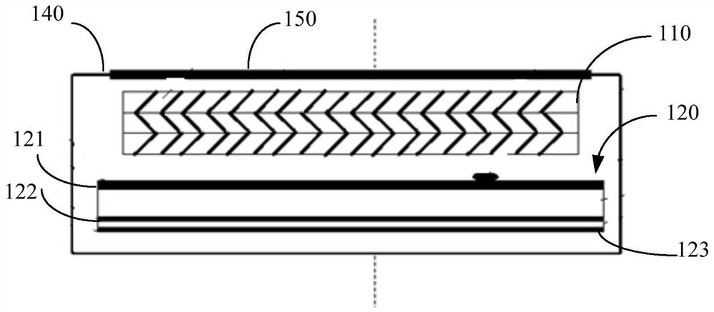
[0021] see figure 1 , is a schematic structural diagram of a photon counting imaging detector 100 provided in an embodiment of the present invention, including: a plurality of stacked microchannel plates 110, a position coding anode 120 located below the microchannel plate 110, and the position coding anode 120 includes a position coding anode electron group receiving layer 121, a position coding anode charge sensing layer 122 and a position coding anode capac...


PUM


Abstract

The photon counting imaging detector provided by the present invention includes a plurality of stacked microchannel plates, a position-coded anode located under the microchannel plate, and the position-coded anode includes a position-coded anode electron group receiving layer, a position-coded anode charge A sensing layer and a position-coding anode capacitance conducting layer, between the position-coding anode electron group receiving layer and the position-coding anode charge-sensing layer and between the position-coding anode charge-sensing layer and the position-coding anode capacitance conducting layer All are provided with an insulating medium, and the microchannel plate, the position-coded anode electron group receiving layer, the position-coded anode charge sensing layer and the position-coded anode capacitance conduction layer are all set in a vacuum chamber. Photon counting imaging detectors can simultaneously achieve high imaging resolution and high photon count rate.

Description

technical field [0001] The invention relates to the technical field of imaging detection of weak and extremely weak targets, in particular to a photon counting imaging detector. Background technique [0002] In important fields such as space astronomy, particle detection, and bioluminescent imaging, researchers have more and more demands for the detection of weak targets or particles, and are becoming more and more urgent. Imaging of such targets requires the use of photon-counting-based imaging detectors. The photon counting imaging detector can record the spatial position information of a single photon or charged particle, and realize the detection of the target radiation by counting and accumulating. It has the advantages of ultra-low noise and ultra-high sensitivity, and can image and detect faint targets through long-term photon counting imaging. [0003] The photon counting imaging detector is generally composed of a photoelectric conversion-electron multiplication m...

Claims


Application Information

Patent Timeline
Patent Type & Authority Patents(China)
IPC IPC(8): G01J11/00
CPCG01J11/00
Inventor 何玲平陈波张宏吉刘世界
Owner CHANGCHUN INST OF OPTICS FINE MECHANICS & PHYSICS CHINESE ACAD OF SCI
Why Eureka
Try Eureka