Welding waveform control method for gas metal arc welding of nickel-based alloy

A technology of melting electrode gas and nickel-based alloys, applied in welding equipment, welding accessories, manufacturing tools, etc., can solve the problems of difficult droplet transfer, poor welding effect, incomplete droplet transfer, etc., to achieve all-position welding, The effect of high deposition efficiency and low cost

Active Publication Date: 2019-10-25
SHANGHAI JIAO TONG UNIV
View PDF5 Cites 7 Cited by
  • Summary
  • Abstract
  • Description
  • Claims
  • Application Information

AI Technical Summary

Problems solved by technology

[0010] In view of the above-mentioned defects of the prior art, the technical problem to be solved by the present invention is that under conventional P-GMAW, the droplet transfer is difficult, a large amount of spatter will be formed, and the droplet transfer is incomplete, and the welding effect is poor

Method used


Image

  • Welding waveform control method for gas metal arc welding of nickel-based alloy
  • Welding waveform control method for gas metal arc welding of nickel-based alloy
  • Welding waveform control method for gas metal arc welding of nickel-based alloy

Examples


Embodiment 1

[0048] In the S-P-GMAW welding method, welding current control is the core technology to suppress spatter. like Figure 4 As shown, the present invention provides a preferred embodiment of a welding waveform control method for gas metal arc welding of nickel-based alloys. The specific control period corresponds to the welding process.

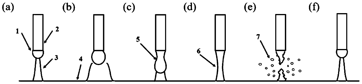
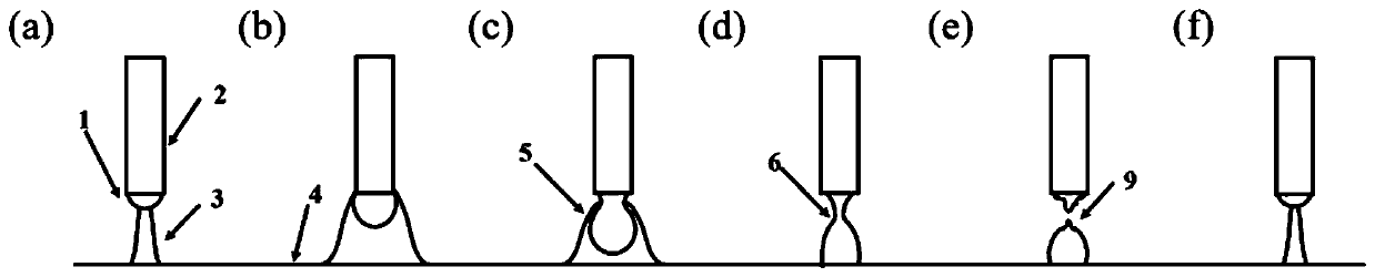
[0049] Figure 4 Stage A is the base value stage (corresponding to image 3 -a): Set the welding voltage to 20V, the welding current to 35A, and the duration t 1 Set it to 8ms to maintain stable combustion of arc 3;

[0050] Figure 4 Middle B stage is the early stage of pulse stage (corresponding to image 3 -b): Set welding voltage to 43V, welding current to 480A, duration t 2 Set it to 0.9ms, so that the welding wire 2 melts rapidly, and the droplet 1 grows rapidly;

[0051] Figure 4 Middle C stage is the late stage of pulse stage (corresponding to image 3 -c): Set welding voltage to 44V, welding current to 520A, duration t 3 Se...

Embodiment 2

[0057] like Figure 5 As shown, another preferred embodiment of the method for controlling the welding waveform of a nickel-based alloy gas shielded metal arc welding provided by the present invention. The specific control period corresponds to the welding process.

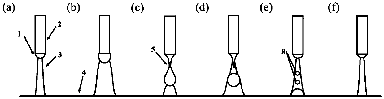
[0058] Figure 5 Stage A is the base value stage (corresponding to image 3 -a): Set welding voltage to 21V, welding current to 40A, duration t 1 Set it to 7.5ms to maintain stable combustion of arc 3;

[0059] Figure 5 Middle B stage is the early stage of pulse stage (corresponding to image 3 -b): Set welding voltage to 41V, welding current to 460A, duration t 2 Set it to 1.0ms, so that the welding wire 2 melts rapidly, and the droplet 1 grows rapidly;

[0060] Figure 5 Middle C stage is the late stage of pulse stage (corresponding to image 3 -c): Set welding voltage to 46V, welding current to 540A, duration t 3 Set to 1.3ms, so that the droplet is elongated and necked;

[0061] Figure 5 The midd...


PUM


Abstract

The invention discloses a welding waveform control method for gas metal arc welding of a nickel-based alloy. The method comprises the following steps: a basic value stage: setting a basic valve voltage, a basic valve current and a duration t1; an earlier stage of a pulse stage: setting a first voltage, a first current and a duration t2; a later stage of the pulse stage: setting a second voltage, asecond current and a duration t3; finish of the pulse stage: setting a basic value voltage, a basic value current and a duration t4; a short-circuit current inhibiting stage: setting a third voltage,a third current and a duration 5; and an arcing stage: setting an arcing voltage, an arcing current and a duration t6. The method can solve the problem that it is difficult for P-GMAW globular transfer and it is difficult to pave a molten bath and also can overcome the defect that the side wall is not fused and the root is not penetrated incompletely. The method is favorable for all-position welding and is automatically, and is relatively high in deposition efficiency.

Description

technical field [0001] The invention relates to the technical field of welding technology, in particular to a welding waveform control method for gas-shielded metal welding of nickel-based alloys. Background technique [0002] Nickel-based alloys have excellent high-temperature or low-temperature performance, good corrosion resistance, and excellent wear resistance, and are widely used in nuclear power, marine, aerospace and other fields. In order to ensure the performance of nickel-based alloys, it is often necessary to strictly control the welding heat input. Especially under non-flat welding conditions, the welding current must be strictly controlled in order to prevent the molten pool from dripping down. Nickel-based alloys have high surface tension and high viscosity. It is difficult to spread the deposited metal during welding, and defects such as incomplete fusion of the side wall and incomplete penetration of the root are prone to occur. At the same time, it is diff...

Claims


Application Information

Patent Timeline
Patent Type & Authority Applications(China)
IPC IPC(8): B23K9/173B23K9/067B23K9/09B23K9/133B23K9/32
CPCB23K9/067B23K9/09B23K9/133B23K9/173B23K9/32
Inventor 华学明刘轶玮李芳张跃龙蔡艳沈忱
Owner SHANGHAI JIAO TONG UNIV
Why Eureka
Try Eureka