A kind of slag cleaning device for numerical control machine tool

A CNC machine tool and slag cleaning technology, which is used in metal processing machinery parts, metal processing equipment, maintenance and safety accessories, etc. It can solve the problems that iron filings cannot be cleaned, the tool has no cooling structure, and it is not easy to clean, and the waiting time is reached. less, reduce work intensity, increase the effect of service life

Active Publication Date: 2021-03-02
临沂金盛机械配套有限公司
View PDF6 Cites 0 Cited by
  • Summary
  • Abstract
  • Description
  • Claims
  • Application Information

AI Technical Summary

Problems solved by technology

However, in the process of realizing the present invention, the inventors have found that at least the following problems in the prior art have not been resolved: 1. Iron filings are cleaned only by the brush, and because the brush is circular, it is not easy to clean it up when cleaning ; 2. Iron filings cannot be cleaned during processing; 3. The tool does not have a cooling structure, so the tool cannot be well maintained

Method used


Image

  • A kind of slag cleaning device for numerical control machine tool
  • A kind of slag cleaning device for numerical control machine tool
  • A kind of slag cleaning device for numerical control machine tool

Examples


Embodiment 1

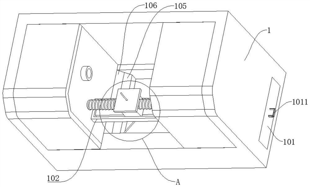
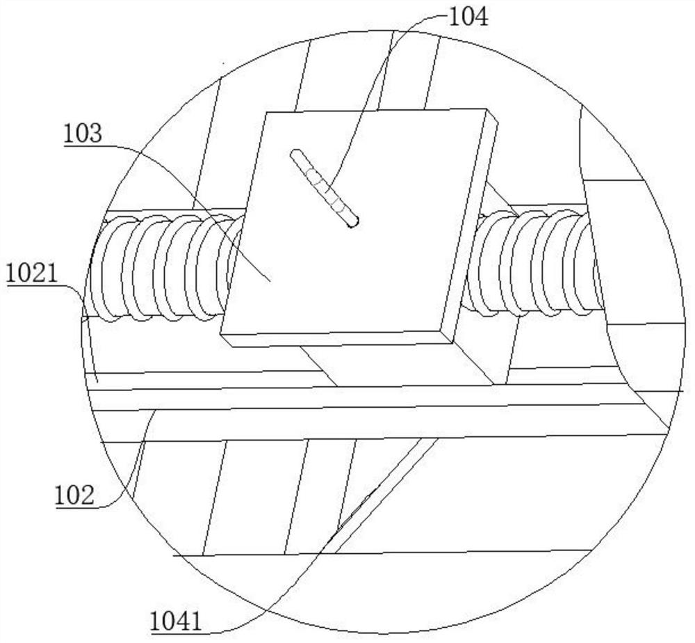
[0035] refer to Figure 1-10, a slag removal device for a numerically controlled machine tool, comprising a machine tool part 1, a sliding support bar 102 is fixedly connected to the machine tool, a tool holder 103 is fixedly connected to the sliding support bar 102, and a stepping motor 2, a collection box 101 is also included. The box 101 is movably connected to the machine tool 1, and the end of the machine tool 1 away from the collection box 101 is slidably connected to a first push plate 106, the stepping motor 2 is fixedly connected to the machine tool 1, and the output end of the stepping motor 2 is fixedly connected to a Screw mandrel 201, the first connecting block 202, the second connecting block 2021 are threadedly connected on the screw mandrel 201, the screw thread direction on the first connecting block 202 and the second connecting block 2021 is opposite, and the first connecting block 202 is connected with the first connecting block 202 in rotation. A telescopi...

Embodiment 2

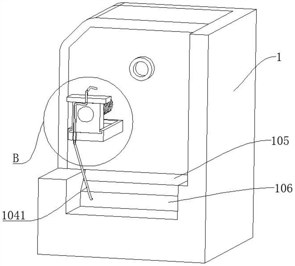
[0045] refer to Figure 1-10 , is basically the same as Embodiment 1, furthermore, it also includes a second push plate 105, the second push plate 105 is slidably connected to the machine tool 1, and the first push plate 106 is slidably connected to the first push plate 105 below the second push plate 105. The side of the push plate 106 close to the second push plate 105 is fixedly connected with a block;

[0046] The end of the second push plate 105 close to the collection box 101 is inclined;

[0047] By the second push plate 105, the waste chips can be pushed farther, and the slope on the second push plate 105 can make the waste chips roll down to the front of the first push plate 106 when the second push plate 105 is not moving. , so that the effect of cleaning debris is better.

Embodiment 3

[0049] refer to Figure 1-10 , is basically the same as Embodiment 1, the difference is that the first piston cylinder 3 includes a first piston cylinder 301, a third piston cylinder 303, the third piston cylinder 303 is slidably connected in the first piston cylinder 301, and the first piston cylinder One end of the barrel 301 away from the third piston barrel 303 is fixedly connected to the machine tool 1, and the end of the third piston barrel 303 away from the first piston barrel 301 is fixedly connected to the first push plate 106. Gas port 3001 matches.

[0050] When the first push plate 106 pushes the waste, the first push plate 106 will pull the third piston barrel 303 to slide in the first piston barrel 301, and then the space in the first piston barrel part 3 will increase, and the outside air will pass through the machine tool parts. 1. The first air inlet 3001 enters into the first piston cylinder 3, and the gas at the working place of the cutter can enter the fir...


PUM


Abstract

The invention discloses a slag removal device for a numerically controlled machine tool, which belongs to the technical field of slag removal devices. A slag removal device for a numerically controlled machine tool, comprising machine parts, a sliding support rod fixedly connected to the machine tool, a tool holder fixedly connected to the sliding support rod, a stepping motor, a collection box, the collection box It is movably connected to the machine tool, the end of the machine tool away from the collection box is slidably connected to a first push plate, the stepping motor is fixedly connected to the machine tool, and the output end of the stepping motor is fixedly connected to a screw rod, A first connecting block and a second connecting block are threadedly connected to the screw rod; the present invention can clean up the waste chips on the tool when processing the workpiece, can cool the tool and the workpiece, and can simultaneously clean the waste chips. Collect, do not need to clean up after processing, improve work efficiency, reduce labor intensity, the product quality of the workpiece is higher, and the life of the tool is longer.

Description

technical field [0001] The invention relates to the technical field of slag removal devices, in particular to a slag removal device for a numerically controlled machine tool. Background technique [0002] Existing CNC machine tools use cutting tools to process workpieces. During the processing, part of the cutting workpiece waste will fall, and part will stay on the cutting tool, and the debris on the cutting tool will affect the quality of the processed workpiece, and the processing When the tool rubs against the workpiece, heat will be generated, and the workpiece may need to wait for time to be removed, which affects the work efficiency and the quality of the processed product is not good; [0003] Existing patent (publication number: CN109434549A) discloses a kind of machine tool chip removal and cleaning device for CNC machine tools, including ash accumulation box, ash filter tube, cover plate, first threaded rod, backing plate, mounting frame, sprocket wheel, slider ,...

Claims


Application Information

Patent Timeline
Patent Type & Authority Patents(China)
IPC IPC(8): B23Q11/00
CPCB23Q11/0042
Inventor 马建伟董有松
Owner 临沂金盛机械配套有限公司
Why Eureka
Try Eureka