Automatic processing production line for surface grinding of clutch facing

A technology for automatic processing of clutch faces, applied in the direction of grinding feed movement, grinding workpiece support, metal processing equipment, etc., can solve the problems of cumbersome grinding procedures, low grinding efficiency, large floor space, etc., and achieve thorough grinding The effect of uniformity, increasing processing efficiency, reducing investment and floor space

Pending Publication Date: 2019-10-25
浙江科马摩擦材料股份有限公司
View PDF1 Cites 2 Cited by
  • Summary
  • Abstract
  • Description
  • Claims
  • Application Information

AI Technical Summary

Problems solved by technology

[0003] Most of the processing of the clutch face is to impregnate the composite fiber thread in the resin, and then impregnate it in the glue. After winding, it is hot-pressed for further heat treatment, and then processed by grinding, dedusted and marked, and finally inspected. Most of the grinding process of the packaging and the clutch surface is polished with a grinding wheel. The existing patent number is CN201510962885.8, a manufacturing equipment and method for the steel friction plate of the clutch, which solves the problem that has not yet been realized in the current production process of the friction plate. The manufacturing equipment that automatically grinds both sides of the friction plate separately, but the friction plate is still ground separately on both sides, the grinding efficiency is low, and the equipment for grinding the two sides separately occupies a large area, the investment in equipment is large, and the grinding procedure is cumbersome and requires two steps. , for this reason, we propose an automatic processing line for clutch face surface grinding

Method used


Image

  • Automatic processing production line for surface grinding of clutch facing
  • Automatic processing production line for surface grinding of clutch facing
  • Automatic processing production line for surface grinding of clutch facing

Examples


Embodiment Construction

[0022] The following will clearly and completely describe the technical solutions in the embodiments of the present invention with reference to the accompanying drawings in the embodiments of the present invention. Obviously, the described embodiments are only some, not all, embodiments of the present invention. Based on the embodiments of the present invention, all other embodiments obtained by persons of ordinary skill in the art without making creative efforts belong to the protection scope of the present invention.

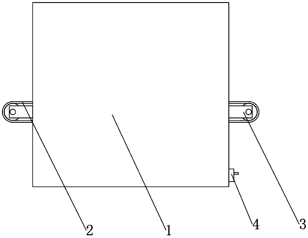
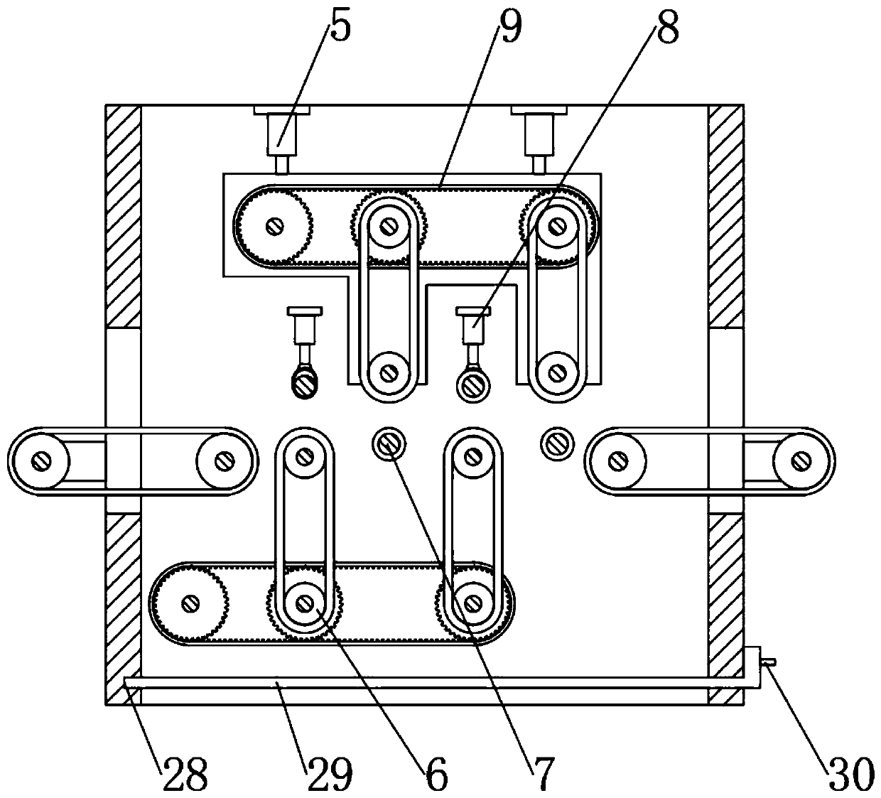
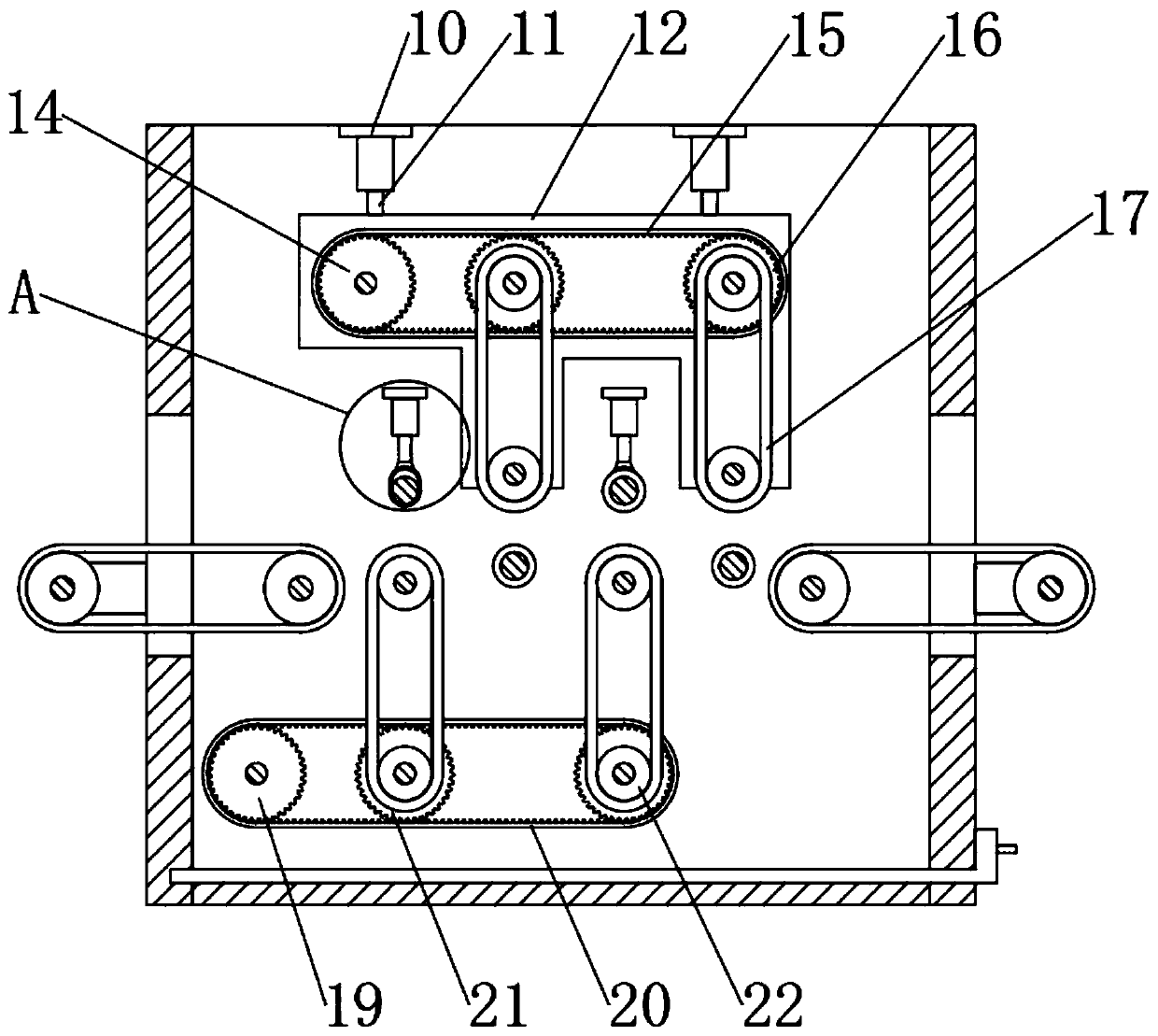
[0023] see Figure 1-5 , the present invention provides a technical solution: an automatic processing line for clutch surface grinding, including an equipment casing 1, a feed conveyor belt 2, a discharge conveyor belt 3, a waste collection device 4, a moving device 5, a fixing device 6, a transmission wheel 7 and A pressing device 8, a feeding conveyor belt 2 is fixed on one side of the equipment casing 1, a moving device 5 is arranged on one side of the feed...


PUM


Abstract

The invention discloses an automatic processing production line for surface grinding of a clutch facing. The automatic processing production line for surface grinding of the clutch facing comprises anequipment shell, a feeding conveyor belt, a discharging conveyor belt, a waste collecting device, a moving device, a fixing device, a transmission wheel and a pressing device, wherein the feeding conveyor belt is fixed to one side of the equipment shell; the moving device is arranged at one side of the feeding conveyor belt and is fixedly connected to the equipment shell; the fixing device is arranged at the bottom of the moving device and is fixedly connected to the equipment shell; and the pressing device is arranged between the moving device and the fixing device. According to the automatic processing production line for surface grinding of the clutch facing, the double-sided grinding of the clutch facing is realized by the device; the limit grinding is realized during grinding; the grinding is relatively thorough and uniform; the processing quality is ensured; moreover, the double-sided grinding simplifies the clutch facing grinding process; the input and floor space of the deviceare reduced; and the processing efficiency of the clutch facing is improved.

Description

technical field [0001] The invention relates to the technical field of clutch face sheet processing, in particular to an automatic processing line for clutch face sheet grinding. Background technique [0002] The clutch face is a composite material with friction as the main function and structural performance requirements. The friction material for automobiles is mainly used to manufacture brake friction plates and clutch faces. These friction materials used to be asbestos-based friction materials. As the requirements for environmental protection and safety are getting higher and higher, semi-metallic friction materials, composite fiber friction materials, and ceramic fiber friction materials are mostly used now. [0003] Most of the processing of the clutch face is to impregnate the composite fiber thread in the resin, and then impregnate it in the glue. After winding, it is hot-pressed for further heat treatment, and then processed by grinding, dedusted and marked, and fin...

Claims


Application Information

Patent Timeline
Patent Type & Authority Applications(China)
IPC IPC(8): B24B21/00B24B21/12B24B21/18B24B41/00B24B41/02B24B41/06B24B55/12
CPCB24B21/008B24B21/12B24B21/18B24B41/005B24B41/02B24B41/06B24B55/12
Inventor 廖翔宇徐长城程慧玲王宗和徐英廖清云李斌毛坚彭勇成吴晓
Owner 浙江科马摩擦材料股份有限公司
Why Eureka
Try Eureka