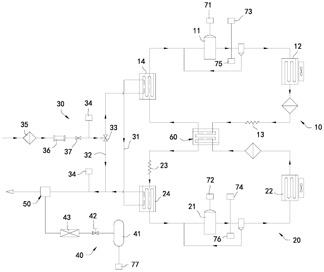
Low-temperature cold air refrigeration system and control method thereof as well as minimal quantity lubrication cooing system

A refrigeration system and cold air technology, applied in refrigerators, refrigeration components, refrigeration and liquefaction, etc., can solve the problems of increasing the air output of cold air, not being widely used in large areas, and only reducing to -30 °C.

Inactive Publication Date: 2019-10-25
CONPROFE TECH GRP CO LTD +1
View PDF6 Cites 5 Cited by
  • Summary
  • Abstract
  • Description
  • Claims
  • Application Information

AI Technical Summary

Problems solved by technology

However, the cost of carbon dioxide cryogenic cooling and liquid nitrogen cooling is relatively high, and it has not yet been widely used
In the prior art, in the air-cooled metal machining process, the cold air is mainly provided by the air cooler. The existing air cooler basically has a relatively complicated structure, and the use process is also relatively complicated. The minimum temperature of the cold air can only be reduced to -30°C, not suitable for high-speed and high-precision CNC machine tools
[0004] Patent document CN 102003823A discloses a low-temperature cold air two-stage refrigeration system and its cold air jet machine. Although the two-stage refrigeration structure is adopted, the gas temperature at the outlet of the cold air jet can be effectively reduced to a lower temperature, such as -60°C. However, The overall structure is complex, and the temperature controllability of the cold air outlet is poor; moreover, the air volume of the cold air is limited, and it is difficult to increase the air volume of the cold air while ensuring the temperature of the cold air outlet

Method used


Image

  • Low-temperature cold air refrigeration system and control method thereof as well as minimal quantity lubrication cooing system

Examples


Embodiment Construction

[0022] This part will describe the specific embodiment of the present invention in detail, and the preferred embodiment of the present invention is shown in the accompanying drawings. Each technical feature and overall technical solution of the invention, but it should not be understood as a limitation on the protection scope of the present invention.

[0023] In the description of the present invention, it should be understood that the orientation descriptions, such as up, down, front, back, left, right, etc. indicated orientations or positional relationships are based on the orientations or positional relationships shown in the drawings, and are only In order to facilitate the description of the present invention and simplify the description, it does not indicate or imply that the device or element referred to must have a specific orientation, be constructed and operated in a specific orientation, and thus should not be construed as limiting the present invention.

[0024] I...


PUM


Abstract

The invention discloses a low-temperature cold air refrigeration system and a control method thereof as well as a minimal quantity lubrication cooing system. The low-temperature cold air refrigerationsystem comprises a first refrigeration pipeline, a second refrigeration pipeline and a gas conveying pipeline, the gas conveying pipeline is sequentially connected with a first evaporator of the first refrigeration pipeline and a second evaporator of the second refrigeration pipeline in the flowing direction of compressed gas, so that heat exchange is carried out between the compressed gas and arefrigerant, the gas conveying pipeline is used for conveying the compressed gas to sequentially undergo heat exchange with the first refrigeration pipeline and the second refrigeration pipeline, thecompressed gas is subjected to two times ofheat release in sequence so that the temperature can be effectively reduced, and low-temperature cold air at 60 DEG C below zero at the minimum can be formed. Moreover, two times ofheat exchange is carried out so that full heat exchange can be carried out between the compressed gas and the refrigerant under the condition that the flow velocity of the compressed gas is not reduced.

Description

technical field [0001] The invention relates to the technical field of cooling systems, in particular to a low-temperature cold air refrigeration system, a control method thereof, and a minimal-quantity lubrication cooling system. Background technique [0002] In the process of metal processing, a large amount of heat will be generated due to the cutting friction between the tool and the workpiece, which will affect the machining accuracy of the workpiece and shorten the tool life. The use of low-temperature cooling and lubricating cutting technology has been proven to be an effective solution to solve the difficult-to-process characteristics such as strong cutting thermal shock and vibration of high-hardness and high-strength materials, and plastic materials that are prone to processing burrs. [0003] Currently commonly used cryogenic processing cooling methods include carbon dioxide cryogenic cooling, liquid nitrogen cooling and air cooling processing. However, the cost ...

Claims


Application Information

Patent Timeline
Patent Type & Authority Applications(China)
IPC IPC(8): F25B7/00F25B41/00F25B49/02B23Q11/10F25B41/40
CPCF25B7/00F25B49/02B23Q11/10F25B41/40Y02P70/10
Inventor 颜炳姜李伟秋王勇
Owner CONPROFE TECH GRP CO LTD
Why Eureka
Try Eureka