Radio frequency detection connector and radio frequency detection fixture

A radio frequency detection and connector technology, applied in the direction of testing/measuring connectors, connection, connection/disconnection of connecting devices, etc., can solve the problems of low radio frequency transmission power, small return loss, long transmission line, etc. Effects of high power, high return loss, and short transmission lines

Pending Publication Date: 2019-10-25
SHENZHEN KESHENG COMM TECH
View PDF0 Cites 2 Cited by
  • Summary
  • Abstract
  • Description
  • Claims
  • Application Information

AI Technical Summary

Problems solved by technology

[0003] However, the pogo pin connector has a large radio frequency transmission loss due to the following reasons, which is not enough to meet the accuracy requirements of radio frequency detection
[0004] First, see figure 2 , the structure of the pogo pin connector 20 is relatively complex, and there are many components, which include a coaxial high-frequency connector 250, a signal line 240, a circuit board 230, a spring 220 and an elastic detection needle 210 connected in sequence, and the elastic detection needle 210 is used For connecting antenna and cable products, the coaxial high-frequency connector 250 is used to connect to a network analyzer. The radio frequency signal generated by the antenna cable product needs to pass through the elastic detection pin 210, the spring 220, the circuit board 230, the signal line 240 and the coaxial high-frequency connector 250 In order to reach the network analyzer, there will be reflections between the components due to impedance mismatch. The more components of the connector, the greater the reflectio

Method used


Image

  • Radio frequency detection connector and radio frequency detection fixture
  • Radio frequency detection connector and radio frequency detection fixture
  • Radio frequency detection connector and radio frequency detection fixture

Examples


Embodiment approach

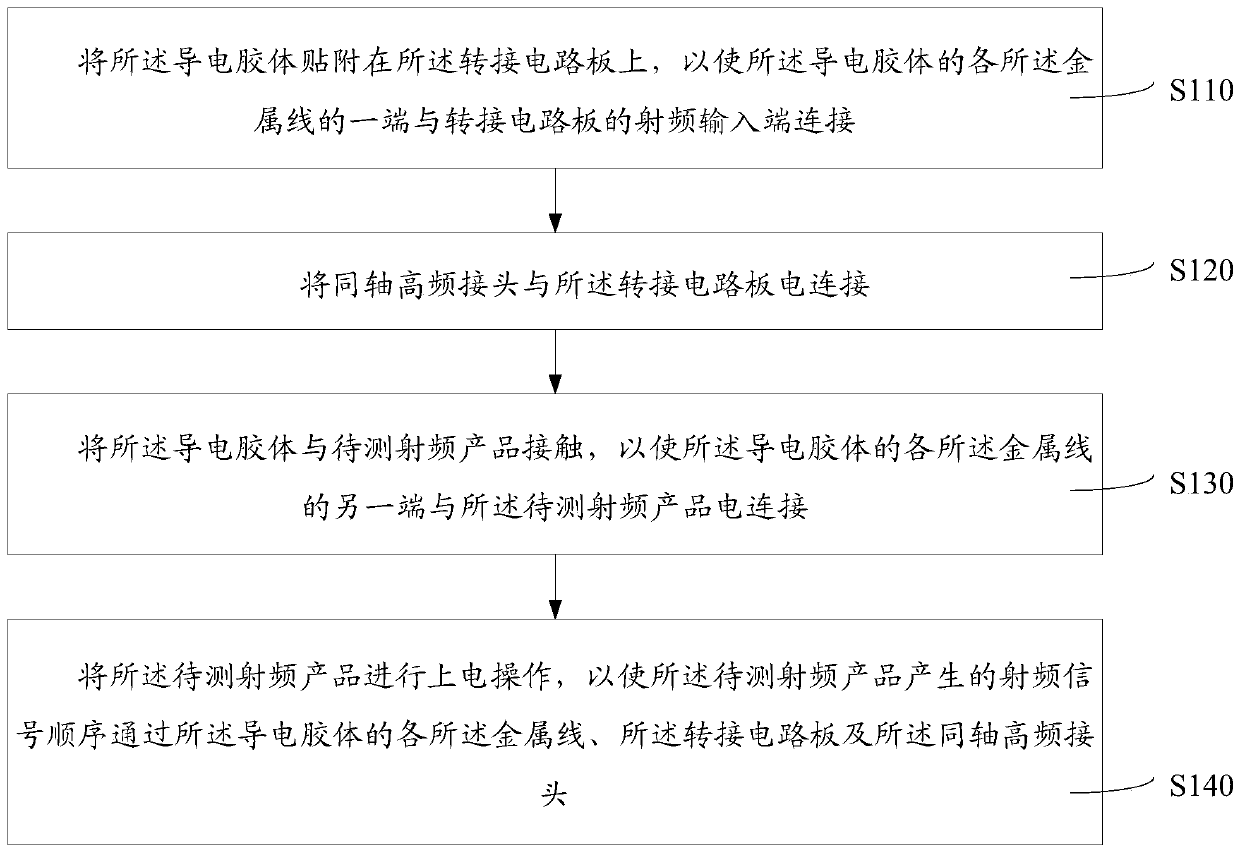
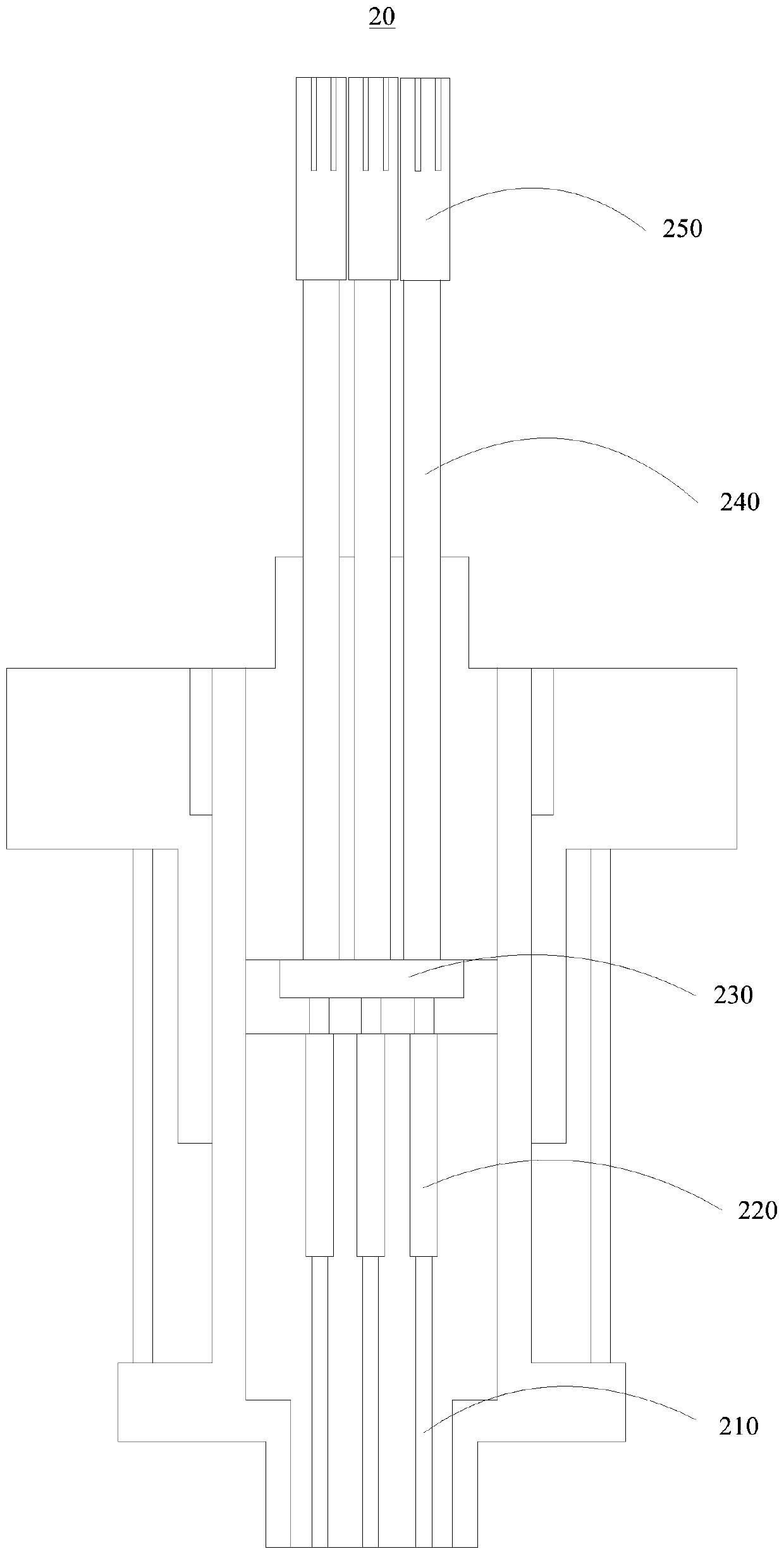
[0047] In one embodiment, the radio frequency detection method based on conductive colloid further includes the following steps: electrically connecting the coaxial high frequency connector to a radio frequency detector, so that the radio frequency signals generated by the radio frequency product to be tested pass through the conductive colloid sequentially. Each of the colloidal metal wires, the transfer circuit board, the coaxial high-frequency connector and the radio frequency detector. It should be noted that the radio frequency detector is a detection device for detecting radio frequency signals, such as a network analyzer. The method utilizes the radio frequency detector to accurately detect the radio frequency signal and display the detection result.

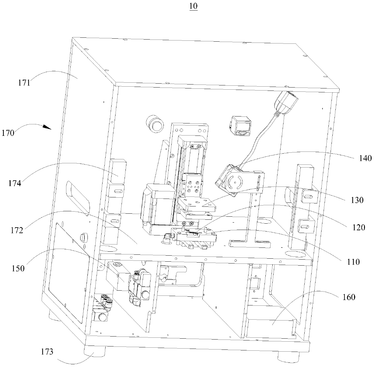
[0048] In one embodiment, the operation of contacting the conductive colloid with the radio frequency product to be tested specifically includes the following steps: placing the radio frequency product to be tested on the...


PUM

PropertyMeasurementUnit
Diameteraaaaaaaaaa

Abstract

The present invention relates to the field of radio frequency detection fixtures, and discloses a radio frequency detection connector and a radio frequency detection fixture. The radio frequency detecting connector comprises a conductive colloid, a switching circuit board and a coaxial high frequency connector, the conductive colloid comprises an insulating colloid and a metal wire set, the metalwire set comprises a plurality of metal wires, and the plurality of metal wires are spaced apart and placed in the insulating colloid, and two ends of each metal wire are respectively exposed outsidethe insulating colloid, and one end of the metal wire is connected to an radio frequency signal input end, and the other end of the metal wire is used to connect with a radio frequency product to be tested; and one end of the coaxial high frequency connector is connected to the switching circuit board, and the other end of the coaxial high frequency connector is used for connection with a radio frequency detector. The radio frequency detection connector is more advanced and precise, has a simpler structure, a shorter transmission line, lower loss of high frequency radio frequency, and can facilitate the radio frequency detector to improve detection accuracy of the radio frequency generated by the radio frequency product to be tested.

Description

technical field [0001] The invention relates to the field of radio frequency detection fixtures, in particular to a radio frequency detection connector and a radio frequency detection fixture. Background technique [0002] Radio frequency (RF) is the abbreviation of Radio Frequency, which means the electromagnetic frequency that can be radiated into space, and the frequency range is from 300kHz to 300GHz. Radio frequency is radio frequency current, referred to as RF, which is an abbreviation of high-frequency alternating electromagnetic waves. The alternating current that changes less than 1,000 times per second is called low-frequency current, and the one that changes more than 10,000 times is called high-frequency current, and radio frequency is such a high-frequency current. When using a radio frequency detector, such as a network analyzer, to perform radio frequency detection on antenna and cable products, since the radio frequency detector cannot be directly connected ...

Claims


Application Information

Patent Timeline
IPC IPC(8): G01R29/08H01R12/72H01R13/22H01R13/46H01R31/06H01R43/26
CPCG01R29/0871G01R29/0878H01R12/722H01R12/727H01R13/22H01R13/46H01R31/065H01R43/26H01R2201/20
Inventor 陈东旭王海旭何进
Owner SHENZHEN KESHENG COMM TECH
Why Eureka
Try Eureka