
Storage box for new energy automobile cell

A technology for new energy vehicles and storage boxes, applied in battery boxes/jackets, secondary batteries, battery pack components, etc. Easy to organize and firmly fixed

Active Publication Date: 2019-10-25
NANTONG INST OF TECH
View PDF13 Cites 1 Cited by
  • Summary
  • Abstract
  • Description
  • Claims
  • Application Information

AI Technical Summary

Problems solved by technology

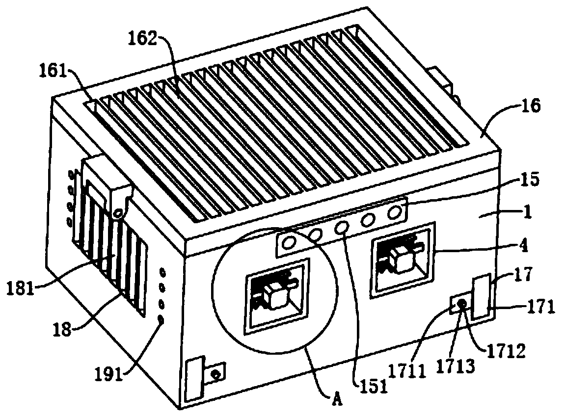
[0004] The above-mentioned drone battery box has the advantage of being able to place batteries of different lengths, but the above-mentioned drone battery box still has some disadvantages, such as: first, because the battery in the box is installed inside the machine , when the machine vibrates, the battery in the box will lose the battery due to the lack of shock absorption capacity; second, the battery placed in the box will generate more heat if it is used for a long time. If the heat is not dissipated in time, it will affect the battery. Third, the lines leading from the battery in the battery box are often not effectively sorted out, and it will appear particularly messy; fourth, the batteries fixed in the box are usually placed directly in the battery box, and cannot be effectively fixed

Method used


Image

  • Storage box for new energy automobile cell
  • Storage box for new energy automobile cell
  • Storage box for new energy automobile cell

Examples


Embodiment 1

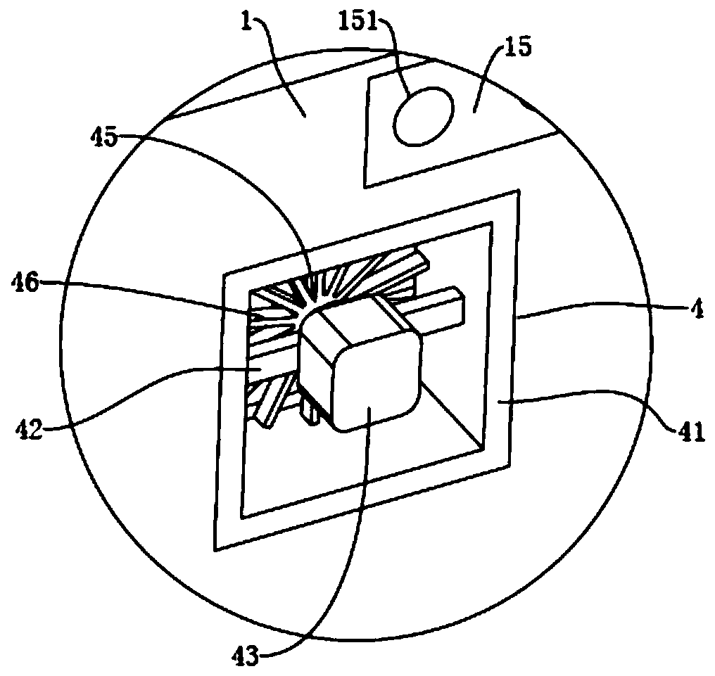
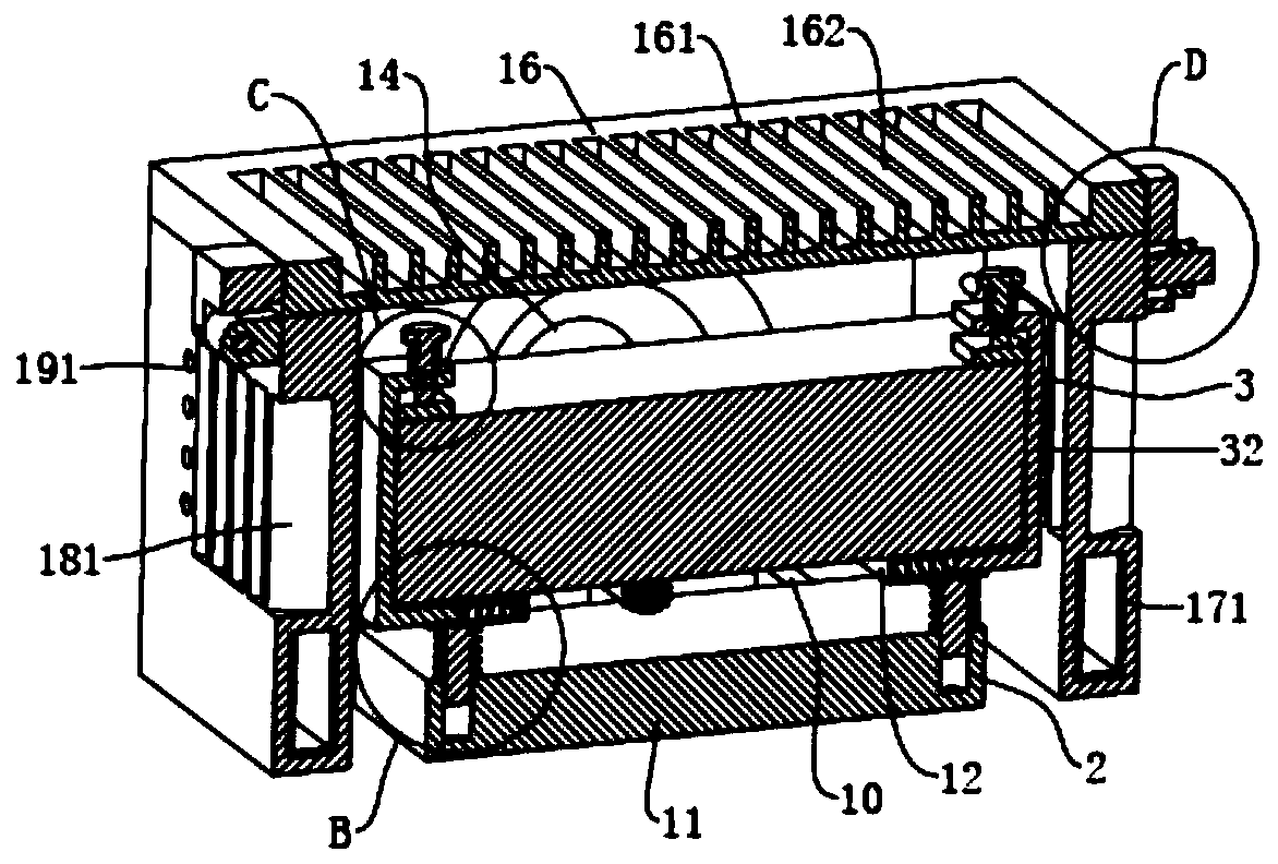
[0054] refer to figure 1 , figure 2 and image 3 , a new energy vehicle battery storage box, including a box body 1 with openings on the top and bottom, and also includes six connecting rods 10 fixed at the opening at the bottom of the box body 1, wherein the six connecting rods 10 are jointly fixed on the support base 11 At the same time, a back-shaped plate 12 is arranged above the support seat 11, and the top of the back-shaped plate 12 is used to place new energy batteries. The battery on the board 12 provides shock absorption; in order to make the battery above the back-shaped board 12 can be firmly fixed, two sets of locking components for fixing the new energy battery placed on the back-shaped board 12 are provided on the back-shaped board 12 3. In order to make the battery in the box body 1 get good heat dissipation, two grooves 13 are opened on one side of the box body 1, and the exhaust assembly 4 is respectively installed and fixed in the two grooves 13, and the ...

Embodiment 2

[0065] The difference from Example 1 is that the surface of the back-shaped plate 12 is also coated with a layer of anti-fouling coating, because the surface of the back-shaped plate 12 needs to place batteries, and the top of the back-shaped plate 12 is easy to accumulate dust, in order to prevent dust Firmly stick on the top of the back-shaped plate 12, the surface of the back-shaped plate 12 is sprayed with a layer of antifouling coating, wherein the antifouling coating is prepared by the following method:

[0066]Take the following raw materials of each component by weight for later use: 80 parts of polytetrafluoroethylene, 40 parts of polycarbonate, 20 parts of sodium laureth sulfate, 20 parts of sodium lauroyl sarcosine, and 15 parts of trihydroxystearin , 20 parts of phenoxyethanol, 10 parts of citric acid, 15 parts of sodium benzoate, 8 parts of sodium chloride, 8 parts of cocoamidomethyl MEA;

[0067] S1. Prepare antifouling coating pre-preparation solution; mix and s...

Embodiment 3

[0073] The difference from Example 2 is the preparation of the back-shaped plate 12 surface antifouling coating, wherein the antifouling coating is prepared by the following method:

[0074] Take the following components by weight for subsequent use: 83 parts of polytetrafluoroethylene, 43 parts of polycarbonate, 23 parts of sodium laureth sulfate, 23 parts of sodium lauroyl sarcosinate, and 18 parts of trihydroxystearin , 22 parts of phenoxyethanol, 10 parts of citric acid, 15 parts of sodium benzoate, 8 parts of sodium chloride, 8 parts of cocamidomethyl MEA;

[0075] S1. Prepare antifouling coating pre-preparation solution; mix polytetrafluoroethylene, polycarbonate and sodium laureth sulfate evenly, then add to the reaction kettle and heat to 291°C, then keep warm for 12min;

[0076] S2. Preparation of antifouling coating solution: Cool the antifouling coating pre-preparation solution obtained in S1 to 207°C, then add sodium lauroyl sarcosinate, trihydroxystearyl essence, ...


PUM

PropertyMeasurementUnit
Thicknessaaaaaaaaaa

Abstract

The invention discloses a storage box for a new energy automobile cell. The storage box is characterized by comprising a box body having openings at the top and the bottom, and further comprising multiple connection rods which are fixed at the bottom opening of the box body and are all fixed on a support base, a hollow-square board arranged above the support base, two grooves which are symmetrically arranged at one side of the box body and are internally fixedly equipped with ventilation assemblies, and a fixing board which is arranged at one side of the box body and is provided with multipleline through holes for penetration of lines, wherein the new energy cell is arranged above the hollow-square board, and a damping assembly is arranged between the hollow-square board and the support base. The storage box is advantaged in that the cell is mounted on the hollow-square board above a support board, when an automobile vibrates, the damping effect on the cell in the box body can be provided for the cell.

Description

technical field [0001] The invention relates to a battery box, in particular to a storage box for a new energy vehicle battery. Background technique [0002] New energy vehicles refer to vehicles that use unconventional vehicle fuels as power sources, integrate advanced technologies in vehicle power control and drive, and form vehicles with advanced technical principles, new technologies, and new structures. The commonly used new energy battery is lithium battery, the working voltage of lithium battery is high, which is three times that of ordinary nickel-cadmium battery hydrogen-nickel battery; its specific energy is large, up to 165WH / kg, which is three times that of hydrogen-nickel battery; It also has the advantages of small size, light weight, long cycle life, low self-discharge rate, no memory effect and no pollution. [0003] Existing publication number is the Chinese patent of CN110021724A, and it discloses a kind of unmanned aerial vehicle battery box, comprises ba...

Claims


Application Information

Patent Timeline
IPC IPC(8): H01M2/10H01M2/06H01M10/613H01M10/625H01M10/6556H01M10/6563
CPCH01M10/613H01M10/625H01M10/6556H01M10/6563H01M50/172H01M50/20Y02E60/10
Inventor 顾平林姜于亮
Owner NANTONG INST OF TECH
Learn More