Fuel cell film electrode catalyst, and preparation method and application thereof

A fuel cell membrane and electrode catalyst technology, applied in fuel cells, battery electrodes, electrochemical generators, etc., can solve the problems of lack of design of three-phase interface channels of catalysts, effective regulation of catalyst lack, and reduction of catalyst reaction areas, etc. Hydrophobic exhaust characteristics, favorable gas transmission, ultra-long stability effect

Inactive Publication Date: 2019-10-25
UNIV OF SCI & TECH OF CHINA
View PDF10 Cites 0 Cited by
  • Summary
  • Abstract
  • Description
  • Claims
  • Application Information

AI Technical Summary

Problems solved by technology

However, when they are assembled into fuel cells and subjected to high-current and long-term discharge tests, their disadvantages are fully exposed: first, traditional catalysts lack effective regulation of electron transport channels, and a lot of conductive agents need to be added to form sufficient electron pathways, these conductive agents reduce the reaction area of ​​the catalyst
Secondly, traditional catalysts do not have a reasonable design of gas transport channels and ion transport channels. The main way to construct gas transport channels is to add hydrophobic polymers such as polytetrafluoroethylene to form a network structure. On the one hand, this method will significantly reduce the conductivity. At the same time, it will also lead to a reduction in the reaction area of ​​the catalyst, which is prone to flooding when a large current is discharged for a long time, which seriously affects the battery life.
[0005] Overall, the main problem affecting the performance of fuel cells with existing membrane electrode catalysts is the lack of reasonable design of catalyst three-phase interface channels.

Method used


Image

  • Fuel cell film electrode catalyst, and preparation method and application thereof
  • Fuel cell film electrode catalyst, and preparation method and application thereof
  • Fuel cell film electrode catalyst, and preparation method and application thereof

Examples


preparation example Construction

[0036] The invention provides a method for preparing a fuel cell membrane electrode catalyst, comprising the following steps:

[0037] S1. Dissolving the transition metal cation source compound in the first solvent to obtain the first solution;

[0038] Dissolving the organic nitrogen-containing ligand in a second solvent to obtain a second solution;

[0039] Dispersing the porous conductive carbon material in a third solvent to obtain a suspension;

[0040] S2. After mixing the first solution and the second solution, they are mixed with the suspension for adsorption, and separated to obtain a solid phase substance;

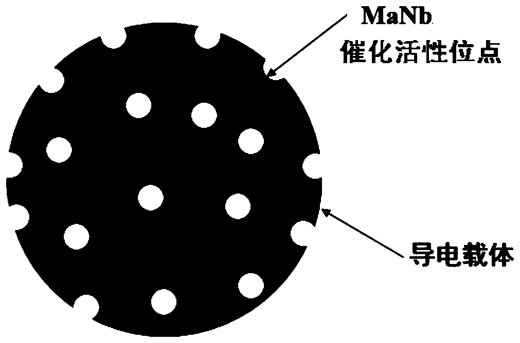
[0041] S3, reacting the solid-phase substance through annealing treatment to obtain a fuel cell membrane electrode catalyst; the fuel cell membrane electrode catalyst includes a porous conductive carbon carrier, and transition metals and nitrogen loaded in the internal pores of the carrier;

[0042] The first solvent and the second solvent are independently sel...

Embodiment 1

[0065] Weigh 0.5g of ferric nitrate, add 30mL of deionized water and 10mL of ethanol into a beaker with a volume of 100mL, and stir for 5 minutes with a magnetic stirrer; weigh 0.1g of polyethyleneimine (Aladdin Company, M.W.600, 99 %, product number E107007-25g, the same as in the following examples) was added into the above mixed solution, and the stirring was continued to obtain the first solution after 10 minutes.

[0066] Weigh 4g of dicyandiamide, add 100mL of deionized water into a beaker with a volume of 500mL, stir with a magnetic stirrer for 30min, and obtain the second solution. Pour the first solution into it, and continue heating and stirring for 1 h to obtain a mixed solution of the first solution and the second solution.

[0067] Add 4 g of conductive carbon black BP2000 (produced by Cabot Corporation of the United States, which can be purchased directly) into 200 mL of ethylene glycol, stir with a magnetic stirrer for 10 min, and then use an ultrasonic cleaner ...

Embodiment 2

[0074] Weigh 0.5g of cobalt nitrate, add 30mL of deionized water and 10mL of ethanol into a beaker with a volume of 100mL, and stir for 5 minutes with a magnetic stirrer; weigh 0.1g of polyethyleneimine and add it to the above mixed solution, and continue stirring , the first solution was obtained after 10 minutes.

[0075] Weigh 1 g of 2,2-bipyridine, add it into a beaker containing 100 mL of deionized water and a volume of 500 mL, stir with a magnetic stirrer for 30 min, and obtain the second solution. Pour the first solution into it, and continue heating and stirring for 1 h to obtain a mixed solution of the first solution and the second solution.

[0076] Add 2 g of conductive carbon black EC-600JD (Lion Corporation, Japan) into 200 mL of ethylene glycol, stir with a magnetic stirrer for 10 min, and then use an ultrasonic cleaner for ultrasonic treatment. After 30 min, a uniformly dispersed suspension is obtained.

[0077] The mixed solution of the first solution and the ...


PUM

PropertyMeasurementUnit
current densityaaaaaaaaaa
particle sizeaaaaaaaaaa
current densityaaaaaaaaaa

Abstract

The invention provides a fuel cell film electrode catalyst, and a preparation method and an application thereof. The method comprises steps that S1, a transition metal cation source compound is dissolved in first solvent to obtain first solution; organic nitrogen-containing ligand is dissolved in second solvent to obtain second solution; a porous conductive carbon material is dispersed in third solvent to obtain suspension; S2, the first solution is mixed with the second solution, then mixed with the suspension, and is adsorbed and separated to obtain solid phase material; and S3, the solid phase material reacts through annealing treatment to obtain the fuel cell film electrode catalyst comprising a porous conductive carbon carrier, and transition metal and nitrogen supported in inner pores of the carrier. The method is advantaged in that the prepared catalyst activity is high, a quite excellent gas-solid liquid three-phase interface is achieved, the method is simple, cost is low, themethod is quite suitable for positive poles of high power metal air cells and fuel cells, and the method has good commercial prospect.

Description

technical field [0001] The invention relates to the technical field of fuel cell catalysts, in particular to a fuel cell membrane electrode catalyst, its preparation method and application. Background technique [0002] Fuel cell is a new type of green energy conversion device that directly converts chemical energy into electrical energy. It has many advantages such as high specific power, high energy conversion efficiency, and no pollution. It is considered to be a key solution to environmental pollution and energy crisis. Transportation vehicles, unmanned aerial vehicles, portable mobile power supplies, emergency backup power supplies, etc. have broad application prospects. A fuel cell is composed of positive and negative electrodes and an electrolyte; its core reaction is the oxidation-reduction reaction on the positive membrane electrode, which generally requires a high-efficiency membrane electrode catalyst with excellent performance. It can be considered that the perf...

Claims


Application Information

Patent Timeline
Patent Type & Authority Applications(China)
IPC IPC(8): H01M4/90H01M8/1004
CPCH01M4/9041H01M4/9083H01M8/1004Y02E60/50
Inventor 吴长征周天培杨波谢毅
Owner UNIV OF SCI & TECH OF CHINA
Why Eureka
Try Eureka