
Motor rotor punching sheet, permanent magnet driving motor rotor body and permanent magnet driving motor

A technology for motor rotor and rotor punching, which is applied in the direction of electric components, magnetic circuit rotating parts, magnetic circuit, etc., can solve the problems of weakening the harmonic magnetomotive force, the effect is not obvious, and the balance of the motor stator and rotor is affected. It achieves the effects of high sine distribution of magnetic field, small influence of harmonic magnetic field, and improved utilization

Pending Publication Date: 2019-10-25
宁波华表机械制造有限公司
View PDF0 Cites 1 Cited by
  • Summary
  • Abstract
  • Description
  • Claims
  • Application Information

AI Technical Summary

Problems solved by technology

[0002] The domestic new energy motor architecture is inherited from the traditional permanent magnet motor architecture. In the traditional permanent magnet motor, due to the inevitable existence of harmonics in the air gap magnetic field, the skewed slot is generally used on the stator and rotor architecture to weaken its influence, but the skewed slot The existence of will further affect the balance between the motor stator and rotor
In addition, distributed windings are often used in traditional permanent magnet motors to weaken the influence of harmonic magnetomotive force, but the effect achieved is not very obvious

Method used


Image

  • Motor rotor punching sheet, permanent magnet driving motor rotor body and permanent magnet driving motor
  • Motor rotor punching sheet, permanent magnet driving motor rotor body and permanent magnet driving motor

Examples


Embodiment 1

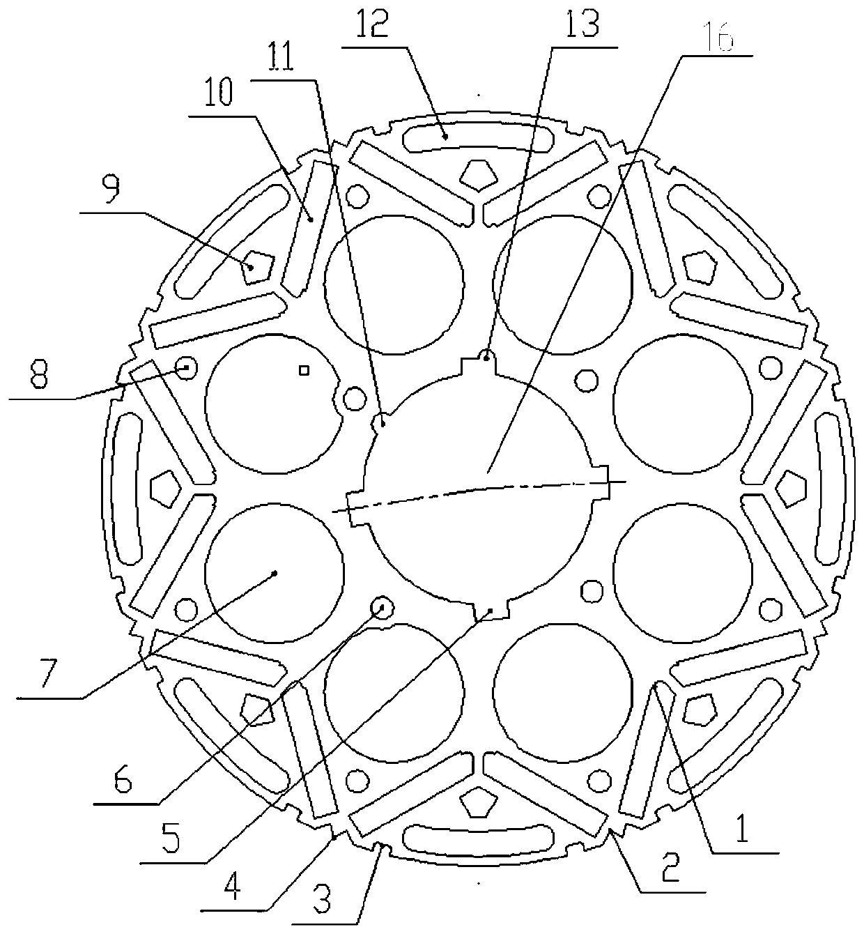
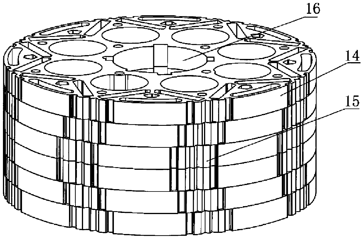
[0026] Such as figure 1 A kind of motor rotor stamping shown, comprises rotating shaft hole 16, is also formed with to place permanent magnet on the rotor stamping, is evenly distributed on the same circumference, and several permanent magnet slots concentric with rotating shaft hole 16, two adjacent permanent magnet slots The magnet slots are combined to form a U-shaped or V-shaped structure, and the permanent magnets are embedded in the permanent magnet slots in an alternating manner of N poles and S poles. The permanent magnet embedded in the rotor body of the motor is segmented, and the height of the rotor is set according to the power, speed, and torque of the permanent magnet motor for vehicles. When running at constant power and high speed, the permanent magnet of the motor has large magnetic flux leakage and weak magnetic speed-up capability Strong, low-speed motor flux leakage is small, the output torque is large, so the torque ripple is small, the control system has ...


PUM


Abstract

The invention discloses a motor rotor punching sheet, a permanent magnet driving motor rotor body and a permanent magnet driving motor, and relates to the technical field of motors. The motor rotor punching sheet comprises a rotating shaft hole, and is further provided with a plurality of permanent magnet grooves which are used for placing permanent magnets and are uniformly distributed on the same circumference and concentric with the rotating shaft hole, two adjacent permanent magnet grooves are combined to form a U-shaped or V-shaped structure, the permanent magnets are embedded into the permanent magnet grooves in an N-pole and S-pole alternating mode, the torque of a rotor combined by the rotor punching sheet approximates a sine wave, and the permanent magnets are distributed along the circumference and embedded in the rotor body in an approximately sine mode, so that the torque ripple is small, the control accuracy of a control system is high, the flux weakening acceleration of apermanent magnet synchronous motor is facilitated, and the performance of the permanent magnets is better improved.

Description

technical field [0001] The invention relates to the technical field of motors, in particular to a motor rotor stamping piece, a permanent magnet drive motor rotor body and a permanent magnet drive motor. Background technique [0002] The domestic new energy motor architecture is inherited from the traditional permanent magnet motor architecture. In the traditional permanent magnet motor, due to the inevitable existence of harmonics in the air gap magnetic field, the skewed slot is generally used on the stator and rotor architecture to weaken its influence, but the skewed slot The existence of will further affect the balance between the motor stator and rotor. In addition, distributed windings are often used in traditional permanent magnet motors to weaken the influence of harmonic magnetomotive force, but the effect achieved is not very obvious. Contents of the invention [0003] In view of this, the present invention discloses a motor rotor stamping, on which are formed ...

Claims


Application Information

Patent Timeline
Patent Type & Authority Applications(China)
IPC IPC(8): H02K1/27
CPCH02K1/276H02K2213/03
Inventor 刘胜恒梁荣陈小良苗鑫
Owner 宁波华表机械制造有限公司
Learn More