Power supply device and charging control method

A technology of power supply and power grid, applied in the direction of circuit devices, battery circuit devices, home appliance efficiency improvement, etc., can solve the problem of large power consumption of mobile terminals, achieve the effects of improving charging efficiency, increasing charging time, and reducing polarization impedance

Inactive Publication Date: 2019-10-25
GUANGDONG OPPO MOBILE TELECOMM CORP LTD
View PDF6 Cites 3 Cited by
  • Summary
  • Abstract
  • Description
  • Claims
  • Application Information

AI Technical Summary

Problems solved by technology

[0002] At present, mobile terminals (such as smart phones) are more and more favored by

Method used


Image

  • Power supply device and charging control method
  • Power supply device and charging control method
  • Power supply device and charging control method

Examples


Embodiment Construction

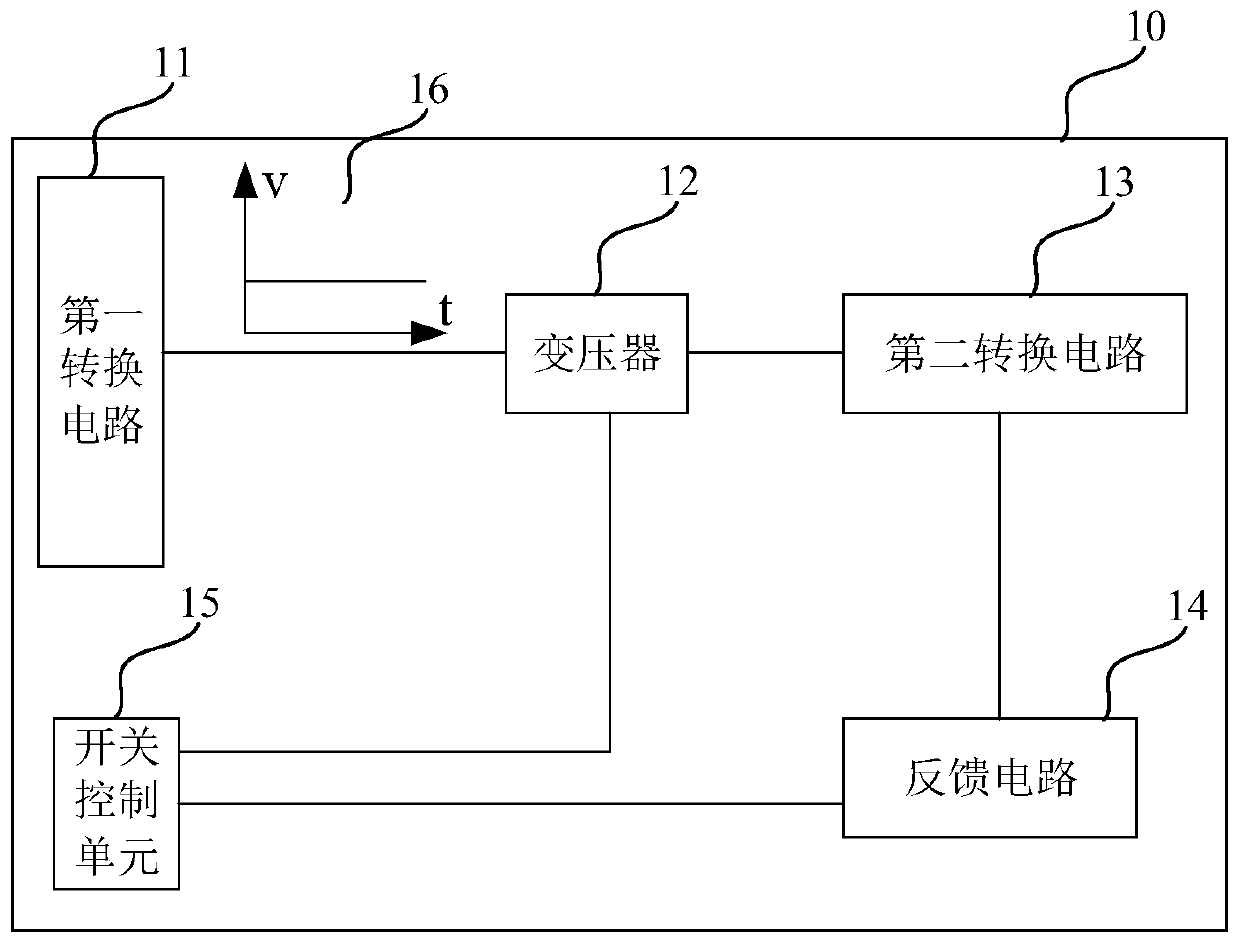
[0013] For ease of understanding, the structure of a traditional power supply device is briefly introduced first.

[0014] Such as figure 1 As shown, a conventional power supply device 10 generally includes a first conversion circuit 11 , a transformer 12 , a second conversion circuit 13 , a feedback circuit 14 and a switch control unit 15 .

[0015] The first conversion circuit 11 is located on the primary side of the transformer 12 , therefore, the first conversion circuit 11 may also be referred to as a primary conversion circuit sometimes. The first conversion circuit 11 may include a rectification circuit and a liquid electrolytic capacitor (such as a liquid aluminum electrolytic capacitor) for filtering. The rectifier circuit and liquid electrolytic capacitor can be used to rectify and filter the alternating current provided by the grid. Since the liquid electrolytic capacitor has a strong filtering capability, the voltage output by the first conversion circuit 11 is u...


PUM


Abstract

The invention provides a power supply device and a charging control method. The power supply device includes: a transformer; a first conversion circuit, which is located on the primary side of the transformer and used for converting alternating current provided by a power grid into voltage in a pulse form; a second conversion circuit, which is located on the secondary side of the transformer and used for generating output current of the power supply device; a feedback circuit, which is used for generating a feedback signal of the output current; and a switch control unit, which is used for controlling the pulse-form voltage according to the power grid synchronizing signal and the feedback signal so that the waveform of the output current is consistent with the waveform of the power grid synchronization signal, wherein the power grid synchronization signal is a signal in a pulse form, the frequency of the power grid synchronization signal is n times or 1/n times of the frequency of thealternating current, and n is a positive integer not less than 1. The output current of the power supply device is set as the current in a pulse form, so that the polarization impedance of the batterycan be reduced, the charging time of the constant-current charging stage is prolonged, and the charging efficiency of the battery can be improved.

Description

technical field [0001] The present application relates to the field of charging, and more specifically, relates to a power supply device and a charging control method. Background technique [0002] At present, mobile terminals (such as smart phones) are more and more favored by consumers, but the mobile terminals consume a lot of power and need to be charged frequently. Therefore, the charging efficiency of batteries has become a hot issue concerned by major manufacturers. Contents of the invention [0003] The present application provides a power supply device and a charging control method, which can improve the charging efficiency of a battery. [0004] According to the first aspect, there is provided a power supply device, including: a transformer; a first conversion circuit, located on the primary side of the transformer, used to convert the alternating current provided by the grid into a pulse form voltage; a second conversion circuit, located on the primary side of ...

Claims


Application Information

Patent Timeline
IPC IPC(8): H02M7/217H02M3/335H02M1/14H02M1/42H02J7/02
CPCH02J7/022H02M1/14H02M1/42H02M3/335H02M7/217H02J7/02H02M1/4258H02M3/33523H02J7/00711H02J2207/20Y02B40/00Y02B70/10H02M1/12
Inventor 邱治维
Owner GUANGDONG OPPO MOBILE TELECOMM CORP LTD
Why Eureka
Try Eureka