Construction method for cast-in-situ bored pile

A technology of bored piles and construction methods, which is applied in the direction of sheet pile walls, foundation structure engineering, construction, etc., can solve the problems of drill pipe offset and affect the efficiency of construction, and achieve clean construction site, fast construction speed and smooth construction. high efficiency effect

Inactive Publication Date: 2019-10-29
BUILDING & MOUNTING ENG CO LTD NO 12 BUREAU MINIST OF RAILWAYS +1
View PDF6 Cites 15 Cited by
  • Summary
  • Abstract
  • Description
  • Claims
  • Application Information

AI Technical Summary

Problems solved by technology

However, during the construction of existing bored piles, there will be a problem of drill pipe offset, so it is necessary to adjust the position of the drill pipe, thereby affecting the efficiency of construction
At the same time, when placing t

Method used


Image

  • Construction method for cast-in-situ bored pile
  • Construction method for cast-in-situ bored pile
  • Construction method for cast-in-situ bored pile

Examples


Embodiment 1

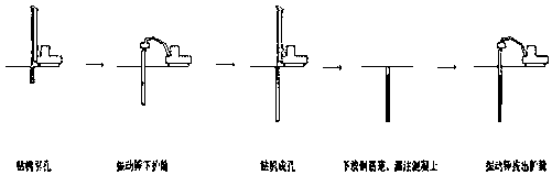
[0042] A construction method for bored piles, comprising the following steps:

[0043] Step 1. Drilling hole:

[0044] Treatment of the base surface of the drilling site: field leveling, removal of surface garbage and obstacles, and obstacles that cannot be drilled, excavated with excavators, backfilled with plain soil and compacted;

[0045] According to the requirements of pile location design drawings, measure and set the pile location and mark it well, draw a circle with a radius of 45cm with the pile location as the center, and check the pile location. The tip is aligned with the center of the pile position to open the pilot hole, the depth of the pilot hole is 7m, and the depth of the pilot hole is selected according to the situation of the grassroots on site. For the grassroots that is soft or easy to collapse, a deeper pilot hole depth is selected.

[0046] Pilot holes can overcome the influence of shallow obstacles. The engineering drilling rig can effectively overc...

Embodiment 2

[0072] A construction method for bored piles, comprising the following steps:

[0073] Step 1. Drilling hole:

[0074] Treatment of the base surface of the drilling site: field leveling, removal of surface garbage and obstacles, and obstacles that cannot be drilled, excavated with excavators, backfilled with plain soil and compacted;

[0075] According to the requirements of pile location design drawings, measure and set the pile location and mark it well, draw a circle with a radius of 45cm with the pile location as the center, and check the pile location. The tip is aligned with the center of the pile position to open a lead hole, and the depth of the lead hole is 6m.

[0076] Pilot holes can overcome the influence of shallow obstacles. The engineering drilling rig can effectively overcome the influence of obstacles, and the obstacles that cannot be drilled through should be dug out with an excavator to prevent damage to the curling of the casing;

[0077] The position of...


PUM

PropertyMeasurementUnit
Diameteraaaaaaaaaa

Abstract

The invention discloses a construction method for a cast-in-situ bored pile. The construction method comprises the following steps: S1, carrying out digging by a drilling machine: processing the surface of a basic layer of a drilling site, and trepanning the basic layer after rechecking a pile position; S2, laying down pile casings by a vibratory hammer: connecting the pile casings by using high strength bolts and nuts; S3, drilling a hole by the drilling machine: after the pile casings arrive a preset depth, carrying out drilling to a designed pile bottom elevation for first time hole cleaning; S4, laying down a reinforcement cage and pouring concrete, carrying out pouring continuously, and overpouring concrete for 1-2 m; and S5, pulling out the pile casings by the vibratory hammer: pulling out the pile casings from pile holes after pouring the concrete, and recycling the pile casings. The method is free of pollution to underground water and tidy in construction site, does not affectthe ambient environment, and meets the high environmental-friendly demand. Compared with a conventional process, the construction speed of the method is over doubled, so that the construction efficiency is high.

Description

technical field [0001] The invention relates to a construction method for bored piles, which belongs to the technical field of construction of pile foundations. Background technique [0002] In order to meet the needs of engineering construction, pile foundations are widely used as the most effective way to improve the bearing capacity of foundations. Pile foundations are generally divided into bored piles and prefabricated piles. Among them, bored piles account for about 70% of the pile foundation construction, and the construction of bored piles is generally divided into dry work and mud wall protection work. However, affected by the environment, the use of mud retaining walls is prohibited in the construction of bored piles in Hong Kong and developed countries in the world. , It is difficult to ensure the stability of the hole wall through mud wall protection. In this case, it is necessary to use the full casing construction technology. [0003] Bored cast-in-situ pile ...

Claims


Application Information

Patent Timeline
IPC IPC(8): E02D5/38
CPCE02D5/38E02D5/385
Inventor 白慧蒋关云靳成周赵远程德勇张煜玺
Owner BUILDING & MOUNTING ENG CO LTD NO 12 BUREAU MINIST OF RAILWAYS
Why Eureka
Try Eureka