Flue gas purification device

A flue gas purification and tracheal technology, which is applied in the field of flue gas treatment, can solve the problem that the flue gas cannot be completely purified, and achieve the effect of improving the filtering effect.

Inactive Publication Date: 2019-11-01
刘欢
View PDF1 Cites 0 Cited by
  • Summary
  • Abstract
  • Description
  • Claims
  • Application Information

AI Technical Summary

Problems solved by technology

[0004] The purpose of the present invention is to provide a flue gas purification device, whic

Method used


Image

  • Flue gas purification device
  • Flue gas purification device

Examples


Embodiment

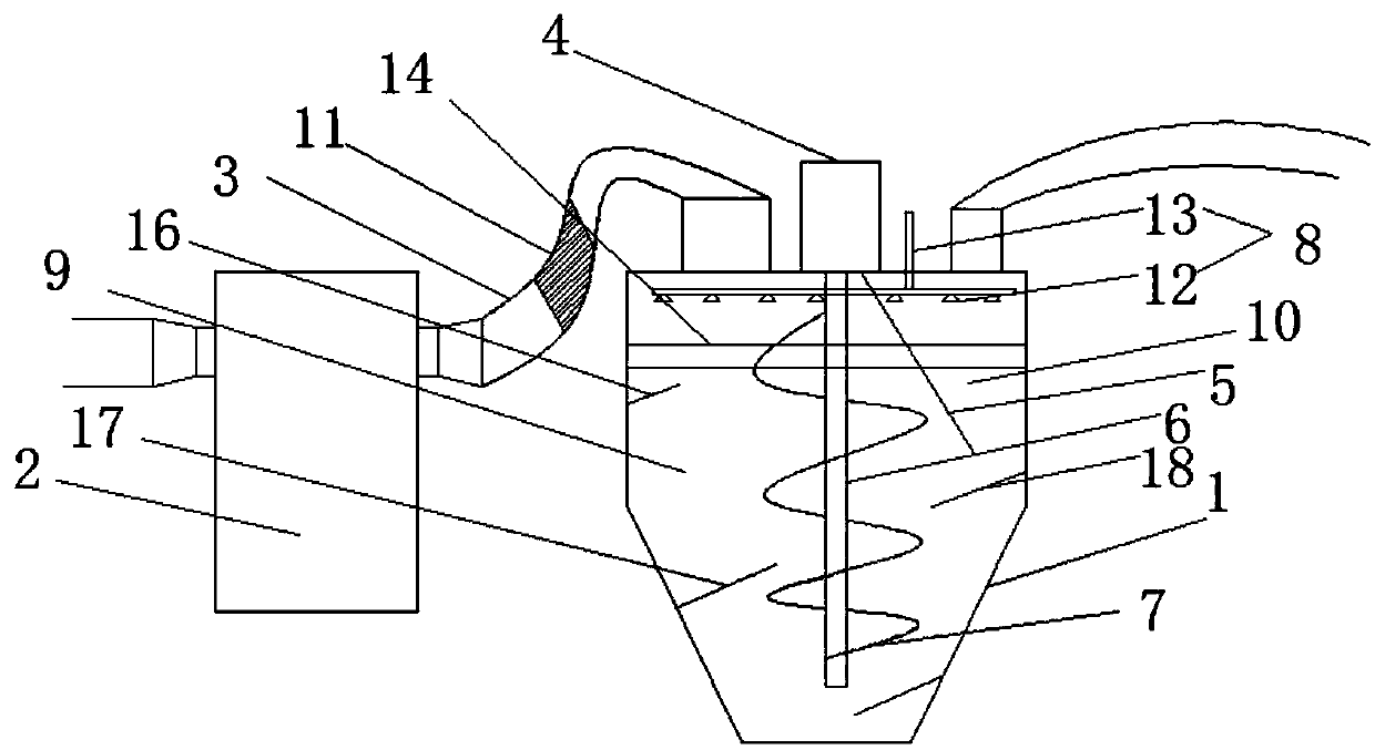
[0026] Such as figure 1 As shown, a flue gas purification device provided by the present invention includes a treatment cylinder 1 and an electrostatic precipitator 2. The electrostatic precipitator 2 communicates with the top of the treatment cylinder 1 through a gas pipe 3. On the treatment cylinder 1 A stirring motor 4 is installed, and the inside of the processing cylinder 1 is provided with an inclined baffle plate 5, the stirring shaft 6 is installed on the stirring motor 4, the stirring blade 7 is installed on the stirring shaft 6, and the inside of the processing cylinder 1 is arranged There is a purification mechanism 8; the electrostatic precipitator 2 is used for the first step of treatment, and the treatment cylinder 1 is used for the second step of treatment.

[0027] Such as figure 1 As shown, the baffle plate 5 divides the processing cylinder 1 into a processing chamber 9 and an air outlet chamber 10. The area of ​​the processing chamber 9 is twice the area of ...


PUM


Abstract

The invention discloses a flue gas purification device. The device comprises a treatment barrel and an electrostatic dust collector, wherein the electrostatic dust collector communicates with the upper part of the treatment barrel through a flue gas pipe, a stirring motor is installed on the treatment barrel, an inclined baffle plate is arranged inside the treatment barrel, a stirring shaft is installed on the stirring motor, stirring blades are installed on the stirring shaft, and a purification mechanism is arranged inside the treatment barrel. The device solves the technical problem that flue gas cannot be completely purified in the prior art.

Description

technical field [0001] The invention relates to the technical field of flue gas treatment, in particular to a flue gas purification device. Background technique [0002] The incinerator is a kind of high-temperature incineration of exhaust gas, waste liquid, solid waste: for example, toxic gas (paint exhaust), toxic rocket liquid fuel, medical waste, domestic waste, animal carcasses, etc., to reduce or reduce the quantification number. It is a kind of environmental protection equipment, and at the same time achieves a product that utilizes part of the heat energy of the incineration medium. Divided into fixed incinerators and mobile incinerators. The principle of the incinerator is to use coal, fuel oil, gas and other fuels to burn and carbonize the objects to be processed at high temperature to achieve the purpose of disinfection. At present, incinerators have great application value in the harmless treatment of sick and injured animal carcasses, as well as in the treatme...

Claims


Application Information

Patent Timeline
IPC IPC(8): F23G5/44F23J15/02F23J15/04
CPCF23G5/44F23J15/022F23J15/025F23J15/04F23J2217/102F23J2219/40
Inventor 刘欢
Owner 刘欢
Why Eureka
Try Eureka