Eureka AIR delivers breakthrough ideas for toughest innovation challenges, trusted by R&D personnel around the world.

Ultra-wideband dual-polarized radiation unit and antenna

A radiating unit and ultra-broadband technology, which is applied to the combination of antenna units with different polarization directions, the structural form of radiating elements, and antennas, can solve the problems of narrow bandwidth of microstrip antennas, large antenna volume, and poor cross-polarization, etc., to achieve Increase isolation, avoid electromagnetic mutual coupling, and improve efficiency

Inactive Publication Date: 2019-11-01
DONGGUAN UNIV OF TECH
View PDF3 Cites 10 Cited by
  • Summary
  • Abstract
  • Description
  • Claims
  • Application Information

AI Technical Summary

Problems solved by technology

[0003] In order to solve the current coexistence of multiple communication standards, at this stage, it is usually achieved by designing a broadband antenna radiating unit or placing multiple frequency band radiating units on one antenna to achieve the broadband characteristics of the antenna, thereby reducing the design cost; but at the same time There are disadvantages such as large volume, heavy weight and high profile of the antenna
Because microstrip antennas have the advantages of low profile, planarization, low cost, and easy processing, microstrip antennas are often designed in the prior art to solve the problems of large antenna volume and high profile, but microstrip antennas also have narrow bandwidth and low gain. Disadvantages such as low and poor cross polarization

Method used


Image

  • Ultra-wideband dual-polarized radiation unit and antenna
  • Ultra-wideband dual-polarized radiation unit and antenna
  • Ultra-wideband dual-polarized radiation unit and antenna

Examples


Embodiment Construction

[0024] In order to describe the content, structural features, achieved goals and effects of the present invention in detail, the following will be described in detail in combination with the embodiments and accompanying drawings.

[0025] In the description of the present invention, it should be understood that the orientation or positional relationship indicated by the terms "upper", "lower", "inner", "outer" and the like are based on the orientation or positional relationship shown in the accompanying drawings, and are only intended to It is convenient to describe the present invention and simplify the description, so it should not be construed as limiting the protection content of the present invention.

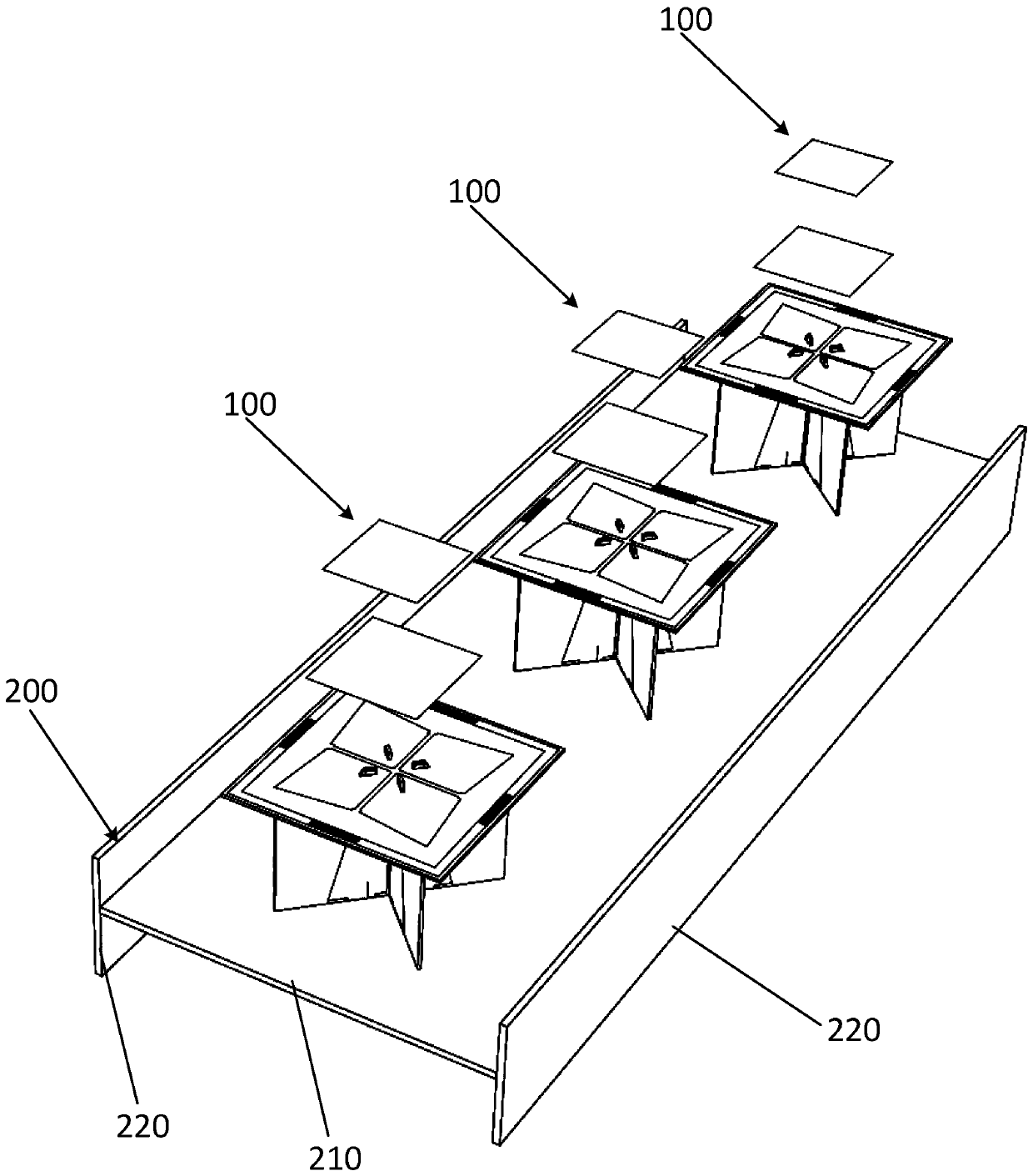
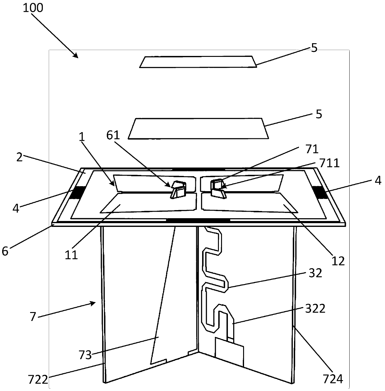
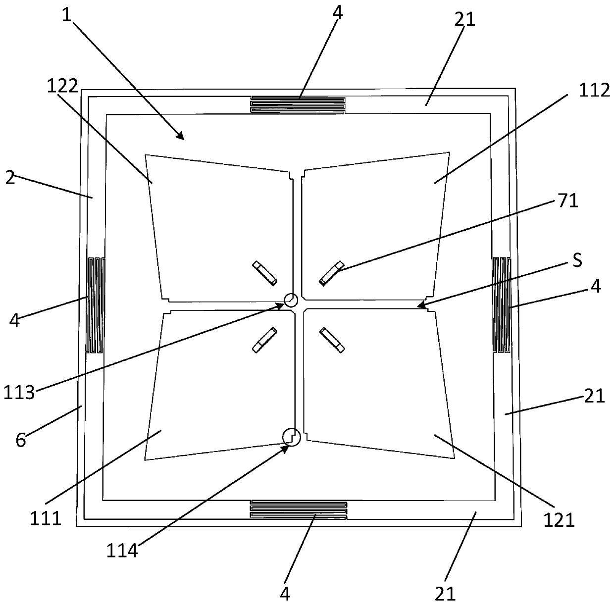
[0026] see Figure 1 to Figure 4 , the embodiment of the present invention discloses an ultra-wideband dual-polarized antenna, which includes a reflector 200 and at least two ultra-wideband dual-polarized radiation units 100, at least two ultra-wideband dual-polarized radi...


PUM


Abstract

The invention discloses an ultra-wideband dual-polarized radiation unit. The antenna comprises a radiating element, a metal ring and a feed element. The metal ring is annularly arranged at the periphery of the radiating element. The radiating element comprises a first dipole and a second dipole which are arranged in a crossed manner. The first dipole and the second dipole respectively comprise tworadiation arms which are arranged diagonally. The feed element comprises a first transmission line and a second transmission line which are electrically isolated. The first transmission line is coupled with the first dipole, and the second transmission line is coupled with the second dipole. According to the invention, the standing-wave ratio and the directional diagram of the radiating element are improved. The bandwidth and the gain of the radiating element are increased. The ultra-wideband design is realized. The radiating element is rotationally and symmetrically arranged around the central position of the radiating element by 90 degrees, so that the structure is compact. The dislocation problem of the antenna in the batch production and assembly process can be avoided. The batch production efficiency is improved. In addition, the invention also discloses an ultra-wideband dual-polarized antenna.

Description

technical field [0001] The invention relates to the technical field of antenna design, in particular to an ultra-wideband dual-polarization radiation unit and an antenna. Background technique [0002] The antenna is a key device for signal transmission and signal reception in the communication system, and its radiation performance and reception performance will directly affect the performance of the entire communication system. With the rapid development of communication technology, it is required to further increase the capacity of the communication system, and the base station antenna is also developing in the direction of broadband, multi-frequency, miniaturization and low cost. Due to the coexistence of multiple communication standards today, the site selection of base station antennas is becoming more and more difficult. Therefore, the layout of the radiation unit of the base station antenna is required to be more compact and smaller. At the same time, the radiation uni...

Claims


Application Information

Patent Timeline
Patent Type & Authority Applications(China)
IPC IPC(8): H01Q1/36H01Q1/38H01Q1/50H01Q1/52H01Q21/00H01Q21/24H01Q19/10
CPCH01Q1/36H01Q1/38H01Q1/50H01Q1/521H01Q19/106H01Q21/0006H01Q21/24
Inventor 陈方园赖颖昕邝伟潮王善进邹园园李家全
Owner DONGGUAN UNIV OF TECH
Why Eureka
Eureka Blog
Learn More