
Automatic punching production line for cylindrical battery steel shell

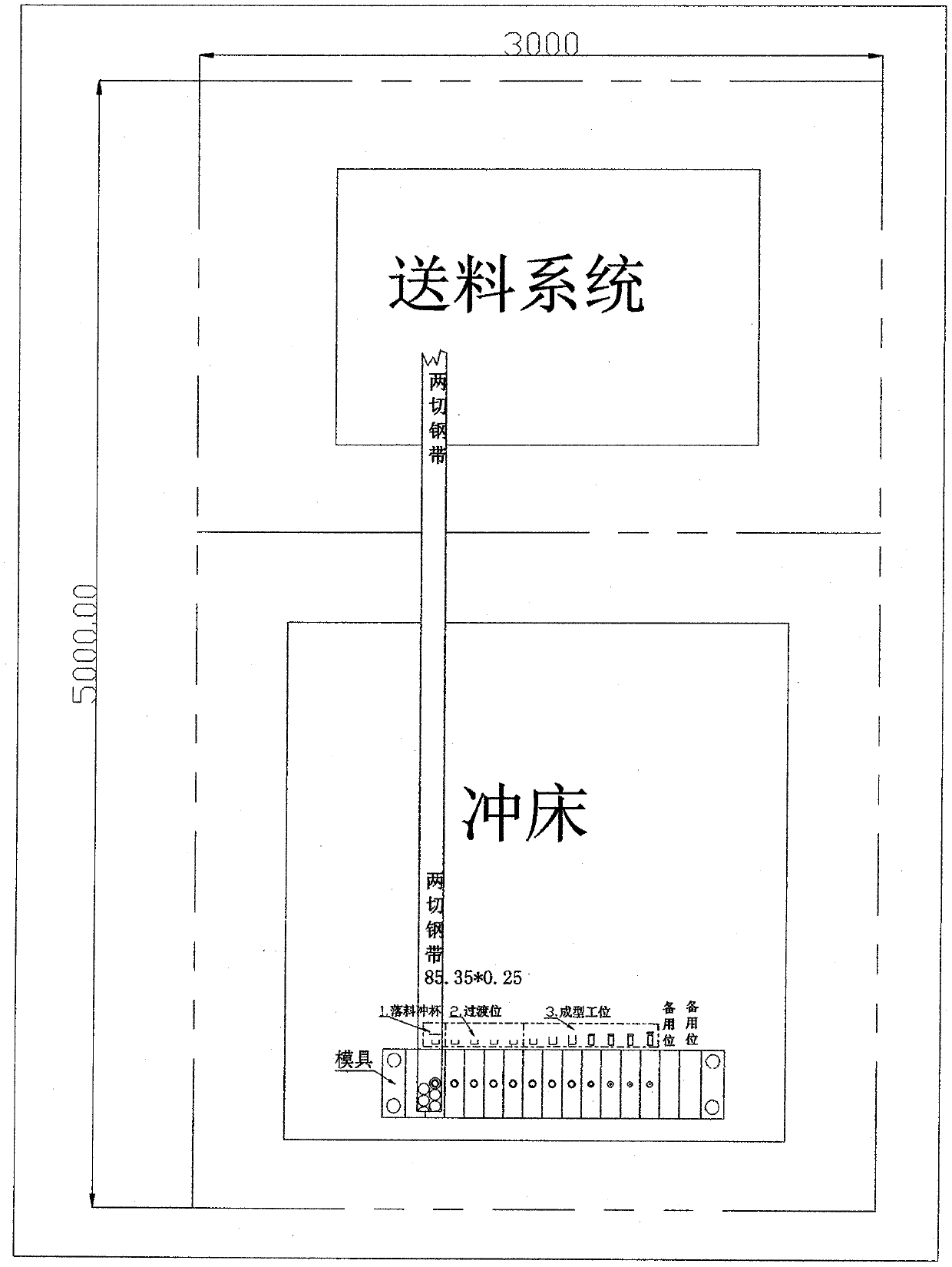
An automated production line, cylindrical battery technology, applied in the direction of cylindrical shell battery/battery, battery pack parts, secondary battery manufacturing, etc., can solve the problems that steel strip materials cannot be used, failures occur, and the utilization rate of materials can no longer be improved. , to achieve the effect of reducing punch failures and product quality problems, and reducing production costs

Pending Publication Date: 2019-11-05
李可
View PDF0 Cites 1 Cited by
  • Summary
  • Abstract
  • Description
  • Claims
  • Application Information

AI Technical Summary

Problems solved by technology

[0003] The technical problem encountered in this way of production is that because the blanking cup and the stretching mold are combined and installed on the same punching machine, due to the relatively fixed size of the working table of the punching machine, more cutting cannot be used for feeding. There are a large number of steel strip materials with a large width, so that the material utilization rate can no longer be improved. For the same reason that the working position is limited, only one set of composite molds can be installed on a single punching machine, and only one product can be produced at a time. In addition, , because the blanking die is designed with a small matching gap between punching and concave dies, high precision, and working conditions such as stamping force, it is difficult to achieve a balance with the working state of the subsequent stretching mold. The blanking and cupping of the first station is often Faults or quality problems occur, resulting in overall production efficiency generally below 80%

Method used


Image

  • Automatic punching production line for cylindrical battery steel shell
  • Automatic punching production line for cylindrical battery steel shell
  • Automatic punching production line for cylindrical battery steel shell

Examples


Embodiment Construction

[0023] The technical solution will be further explained with the example of AA battery steel case and accompanying drawings. The specific embodiments described here are only used to explain the present invention, and are not intended to limit its scope of application. Similar implementations can be applied to cylindrical battery steel cases Such as AAA, 18650, 21700 and other more models.

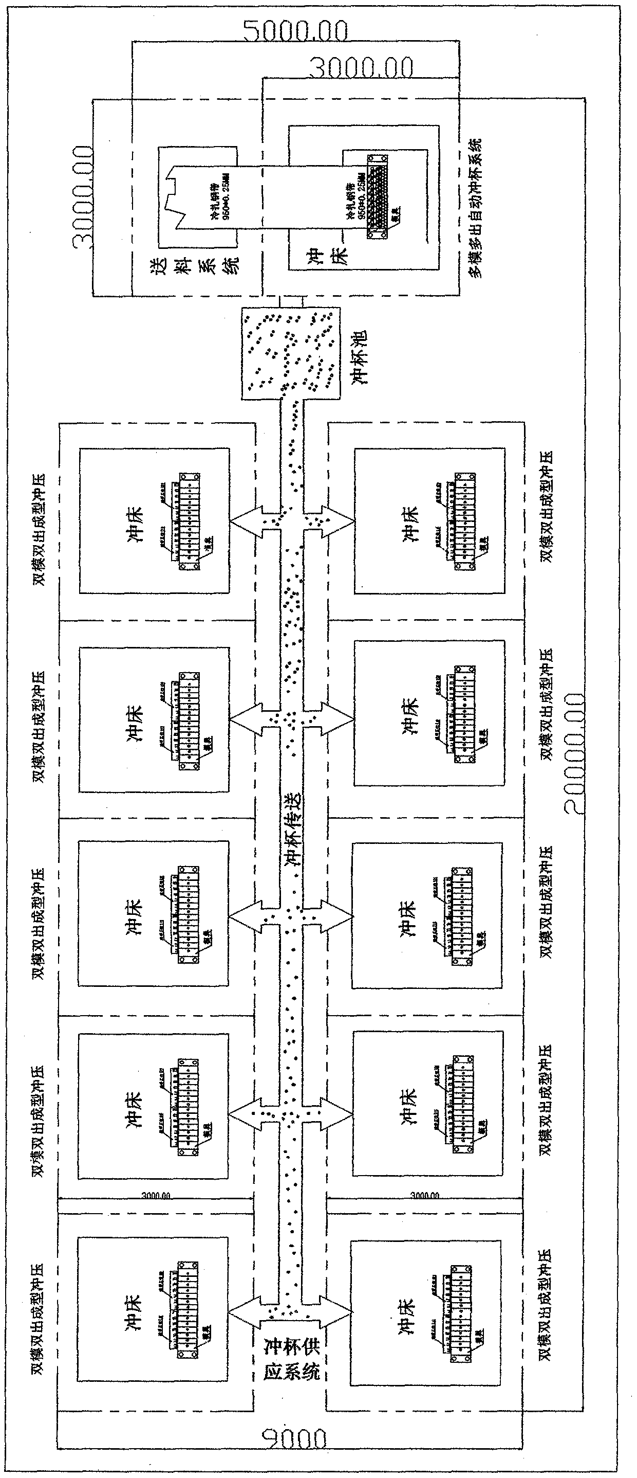
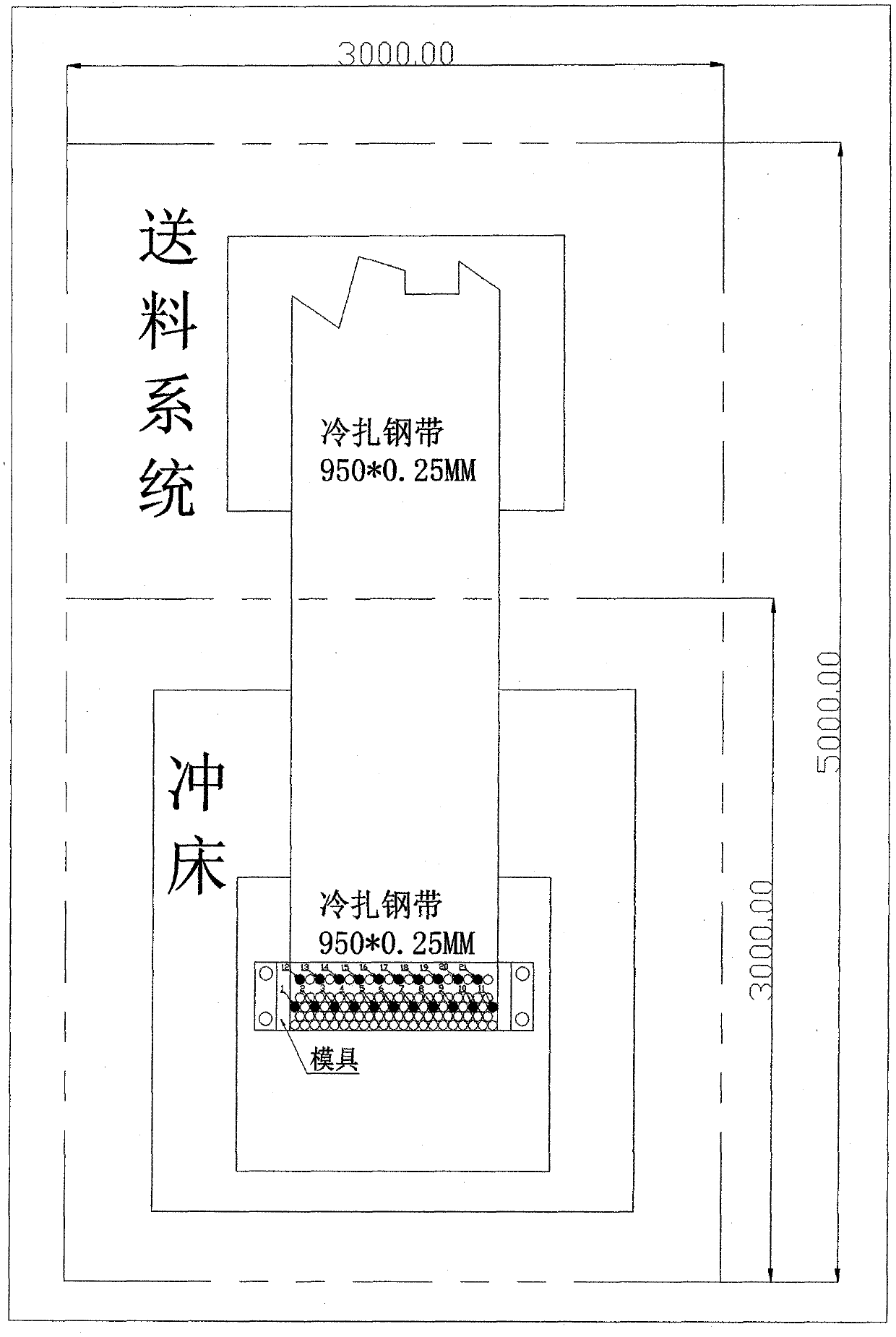
[0024] image 3 , Multi-mode multi-outlet automatic cupping system, referred to as the central cupping system, includes a multi-mode multi-outlet blanking cupping device and a feeding system.

[0025] 1) Figure 4 , 21 Cut blanking and punching cup process mold layout: Take AA battery steel shell as an example, set the blanking diameter to 44.2mm, and take the minimum value of each edge as 1mm. Use the cold-rolled steel strip width of 950mm, assuming that the largest can be arranged along the width direction The number of blanking holes is n, then (44.2+1)n+1=950, and n=21, then the numbe...


PUM


Abstract

The invention relates to the technical field of punching production of battery steel shells, and discloses an automatic punching production line for a cylindrical battery steel shell. The automatic punching production line comprises a multi-mode multi-output automatic cupping system, a cupping supply system and multiple double-mode double-output forming punching machines. Multiple sets of blankingcupping moulds are arranged on a punching machine to realize the centralized multi-mode multi-output automatic blanking cupping, and cupping is supplied to the multiple double-mode double-output punching machines through the cupping supply system to complete forming punching. Compared with the current compound die single-machine single-output automatic punching, the automatic punching productionline for the cylindrical battery steel shell greatly improves the material utilization rate and the production efficiency, the output per machine is doubled, and the product costs, such as the numberof forming punching machines, the area of a production site, direct labor, electricity and oil and other auxiliary materials, are reduced by half.

Description

technical field [0001] The invention relates to the technical field of stamping production of battery steel shells, in particular to an automatic production line for cylindrical battery steel shells. Background technique [0002] With the intensification of competition in various industries and the increase of labor costs, the rapid development of industrial technology and automation has been promoted. Many equipments have achieved a large degree of automated production. For the stamping production of cylindrical battery steel shells, the more advanced production method is composite mold. Single-machine single-out automatic stamping, each punching machine is equipped with a set of composite dies for blanking, cupping and stretching, and a set of feeding system, which can generally realize automatic feeding of 2-cut (less 3-cut) width strips . [0003] The technical problem encountered in this way of production is that because the blanking cup and the stretching mold are com...

Claims


Application Information

Patent Timeline
IPC IPC(8): B21D35/00H01M2/02H01M10/04
CPCB21D35/002H01M10/0422H01M50/107Y02E60/10Y02P70/50
Inventor 李可
Owner 李可
Learn More