Method for treating residual oil through combined technology

A combined process and residual oil technology, which is applied in the treatment of hydrocarbon oil, hydrotreating process, petroleum industry, etc., can solve the problems of inability to process residual oil with high metal content and short operation period

Active Publication Date: 2019-11-05
CHINA PETROLEUM & CHEM CORP +1
View PDF6 Cites 0 Cited by
  • Summary
  • Abstract
  • Description
  • Claims
  • Application Information

AI Technical Summary

Problems solved by technology

However, this method cannot process residue oil with high metal content, or when processing residue oil with high metal content, the operation cycle is short

Method used


Image

  • Method for treating residual oil through combined technology
  • Method for treating residual oil through combined technology
  • Method for treating residual oil through combined technology

Examples


Embodiment 1

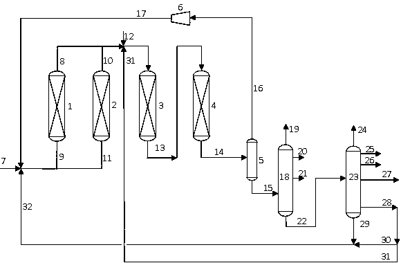
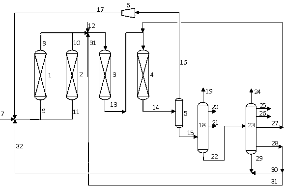
[0081] according to figure 1 In the process flow, the hydrogenation pretreatment reaction zone includes a switchable first hydrogenation pretreatment reaction zone and a second hydrogenation pretreatment reaction zone, the first hydrogenation pretreatment reaction zone is provided with a reactor 1, and the second hydrogenation pretreatment reaction zone is provided with a reactor 1. A reactor 2 is arranged in the second hydrogenation pretreatment reaction zone, and the hydrogenation treatment reaction zone includes a reactor 3 and a reactor 4 arranged in series. According to the material flow direction, the reactor in the hydrogenation pretreatment reaction zone (only one hydrogenation pretreatment reaction zone is online during operation) is filled with catalyst A, catalyst B and catalyst C, and the loading volume ratio of each catalyst is 2:7 : 1. Catalyst B and Catalyst C are installed in the reactor 3 of the hydrotreating reaction zone, and the loading volume ratio of the...

Embodiment 2

[0087] according to figure 1In the process flow, the hydrogenation pretreatment reaction zone includes a switchable first hydrogenation pretreatment reaction zone and a second hydrogenation pretreatment reaction zone, the first hydrogenation pretreatment reaction zone is provided with a reactor 1, and the second hydrogenation pretreatment reaction zone is provided with a reactor 1. A reactor 2 is arranged in the second hydrogenation pretreatment reaction zone, and the hydrogenation treatment reaction zone includes a reactor 3 and a reactor 4 arranged in series. According to the material flow direction, the reactor in the hydrogenation pretreatment reaction zone (only one hydrogenation pretreatment reaction zone is online during operation) is filled with catalyst A, catalyst B and catalyst C, and the loading volume ratio of each catalyst is 3:6 : 1. Catalyst B and catalyst C are housed in hydrotreating reaction zone reactor 3, and the loading volume ratio of two kinds of catal...

Embodiment 3

[0090] according to figure 1 In the process flow, the hydrogenation pretreatment reaction zone includes a switchable first hydrogenation pretreatment reaction zone and a second hydrogenation pretreatment reaction zone, the first hydrogenation pretreatment reaction zone is provided with a reactor 1, and the second hydrogenation pretreatment reaction zone is provided with a reactor 1. A reactor 2 is arranged in the second hydrogenation pretreatment reaction zone, and the hydrogenation treatment reaction zone includes a reactor 3 and a reactor 4 arranged in series. According to the material flow direction, the reactor in the hydrogenation pretreatment reaction zone (only one reactor is online during operation) is filled with catalyst A, catalyst B and catalyst C, and the loading volume ratio of each catalyst is 4:5:1. Catalyst B and Catalyst C are installed in the reactor 3 of the hydroprocessing reaction zone, and the filling volume ratio of the two catalysts is 1:9, and only th...


PUM


Abstract

The invention discloses a method for treating residual oil through a combined technology. The method for treating the residual oil through the combined technology comprises the steps of after inferiorraw material oil and hydrogen are mixed, making an obtained mixture pass through a hydrogenation pre-treatment region at first; and separating a reaction effluent, which is obtained after a reactioneffluent and catalytic cracking circulating oil enter a hydrogenation treatment reaction region, to obtain residual oil subjected to hydrogenation, carrying out a catalytic cracking reaction to obtaincirculating oil and / or slurry oil, and circulating the obtained circulating oil and / or slurry oil to the hydrogenation pre-treatment reaction region, wherein reaction temperature t1 of the hydrogenation pre-treatment reaction region is higher than reaction temperature t2 of the hydrogenation treatment reaction region. By means of the method, the utilization rate of a main catalyst for hydrogenation treatment can be improved, a running period of an integrated device is prolonged, and the running efficiency of the device is improved.

Description

technical field [0001] The invention relates to the field of petroleum refining, in particular to a method for treating inferior residue oil by adopting a combined process of residue oil hydrotreating and catalytic cracking. Background technique [0002] At present, the demand for light and medium oil products in the domestic and foreign oil product markets will continue to rise, while the demand for heavy oil products such as fuel oil will show a downward trend. In addition, due to the increasing pressure of environmental protection, countries have generally raised the quality standard requirements of petroleum products, especially gasoline and diesel products for vehicles. Under the above-mentioned market trend, the refining technology that can not only realize the lightening of heavy oil at a more economical and reasonable price, but also make the obtained products meet the increasingly stringent specifications of gasoline and diesel products has become a key technology d...

Claims


Application Information

Patent Timeline
IPC IPC(8): C10G67/02
CPCC10G67/02
Inventor 吴锐刘涛韩照明黄新露吴长安
Owner CHINA PETROLEUM & CHEM CORP
Why Eureka
Try Eureka