Anti-crystallization compact type urea mixing device

A mixing device and a compact technology, applied in the field of anti-crystallization compact urea mixing device, can solve the problems of high risk of urea crystal blockage and poor mixing effect, reduce the risk of premature wall collision, avoid urea crystallization and mixing The effect of increasing distance

Active Publication Date: 2019-11-05
DONGFENG COMML VEHICLE CO LTD
View PDF7 Cites 9 Cited by
  • Summary
  • Abstract
  • Description
  • Claims
  • Application Information

AI Technical Summary

Problems solved by technology

[0006] The purpose of the present invention is to overcome the problems of poor mixing effect and high risk of urea crystal blockage in the prior art, and to provide a crystallization-proof compact urea mixing device that can effectively improve the mixing effect and avoid urea crystallization

Method used


Image

  • Anti-crystallization compact type urea mixing device
  • Anti-crystallization compact type urea mixing device
  • Anti-crystallization compact type urea mixing device

Examples


Embodiment 1

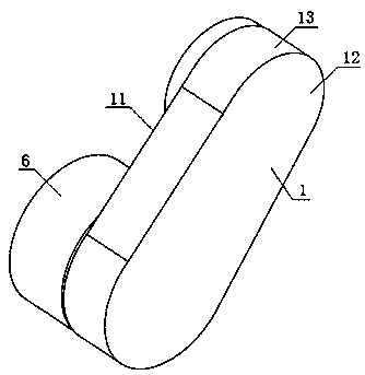
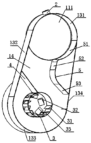
[0039] see Figure 1 to Figure 4 , an anti-crystallization compact urea mixing device, the mixing device includes a No. 1 mixing device 1, and the No. 1 mixing device 1 includes a top plate 11, a bottom plate 12, and an annular side wall 13, and the top plate 11, the bottom plate 12 and the annular The side wall 13 surrounds the inner cavity 14 of the No. 1 mixer 1, and the annular side wall 13 is formed by connecting the No. 1 arc-shaped plate 131, the No. 1 straight plate 132, the No. 2 arc-shaped plate 133, and the No. 2 straight plate 134 sequentially. A through hole 111 connecting the DPF unit and the inner cavity 14 is opened on the top plate 11 near the first arc-shaped plate 131, and the first arc-shaped plate 131 is provided with a The urea injection port 2 arranged on the No. 1 straight plate 132, the inner cavity 14 is provided with the swirl mixer 3 arranged near the No. 2 arc-shaped plate 133, and the sloping plate connecting the outer wall of the swirl mixer 3 an...

Embodiment 2

[0041] The difference with Example 1 is:

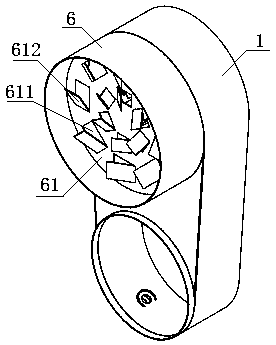
[0042] The mixing device also includes a No. 2 mixing device 6 located between the air outlet 32 ​​and the SCR post-processor. The inside of the No. 2 mixing device 6 is provided with a swirl disc 61, and the outer wall of the swirl disc 61 is in contact with the mixing device. The inner walls of the device 6 are attached together, and a plurality of mixed gas outlets 611 and second swirl vanes 612 corresponding to them are evenly arranged on the swirl disk 61. The inlet and exhaust ends of the mixed gas outlets 611 are respectively connected to the The outlet 32 ​​is in communication with the SCR post-processor, one side of the second swirl vane 612 is fixedly connected to the inner wall of the mixed gas outlet 611, and the other side of the second swirl vane 612 is arranged toward the outside of the No. 2 mixing device 6 .


PUM


Abstract

The invention discloses an anti-crystallization compact type urea mixing device. The device comprises a first mixing device defined by a top plate, a bottom plate, and an annular side wall, wherein the annular side wall is formed by sequentially connecting a first arc-shaped plate, a first straight plate, a second arc-shaped plate and a second straight plate in an end-to-end mode, a through hole communicating with a DPF unit is formed in the position, close to the first arc-shaped plate, of the top plate, a urea injection port communicating with an inner cavity is formed in the first arc-shaped plate, the inner cavity is internally provided with a rotational flow mixer which is arranged near the second arc-shaped plate, an inclined plate which is connected with the outer wall of the rotational flow mixer and the middle of the first straight plate and a baffle plate, the baffle plate is in a C-shaped structure with an opening facing the second straight plate, the two ends of the baffleplate are connected with the first arc-shaped plate and the second straight plate correspondingly, a plurality of airflow inlets are uniformly formed in the side, far away from the baffle plate, of the outer wall of the rotational flow mixer, a plurality of airflow outlets are uniformly formed in the top of the rotational flow mixer, and an S-shaped flow channel is defined by the rotational flow mixer, the inclined plate, the baffle plate and the annular side wall. According to the device, urea is prevented from crystallizing, and the mixing effect is improved.

Description

technical field [0001] The invention belongs to the technical field of automobile engine tail gas purification, and in particular relates to a crystallization-proof compact urea mixing device, which is suitable for improving the mixing effect of urea and tail gas and avoiding urea crystallization. Background technique [0002] Diesel engine exhaust purification treatment system is mainly composed of DPF system and SCR system. The DPF system mainly plays the role of filtering PM in the exhaust gas, and the SCR system is used to catalytically convert NOx in the exhaust gas. The catalytic conversion process is: first spray urea aqueous solution into the mixer located upstream of the SCR catalyst in the SCR system through the nozzle To mix the tail gas and urea conversion products, the mixer then enters the SCR catalyst for catalytic conversion. [0003] Chinese patent: application publication number CN108331643A, application publication date July 27, 2018 The invention patent ...

Claims


Application Information

Patent Timeline
Patent Type & Authority Applications(China)
IPC IPC(8): F01N3/28
CPCF01N3/2892F01N2570/14F01N2610/02
Inventor 刘志辉冯坦王启琛陈镇何胜勇许法亮陈小迅
Owner DONGFENG COMML VEHICLE CO LTD
Why Eureka
Try Eureka