Field detection device, system and method for achieving no maintenance of gas density relay

A gas density and on-site detection technology, which is applied in the electric power field, can solve problems such as potential safety hazards, reduction of insulation strength on the surface of insulating parts, and hazards

Pending Publication Date: 2019-11-05
SHANGHAI ROYE ELECTRICAL CO LTD
View PDF0 Cites 2 Cited by
  • Summary
  • Abstract
  • Description
  • Claims
  • Application Information

AI Technical Summary

Problems solved by technology

3) When the temperature drops, too much moisture may form condensation water, which will significantly reduce the insulation strength of the surface of the insulating part, or even flashover, causing serious damage
In addition, if the on-site inspection of the inspectors is not performed in a standardized manner, there are still potential safety hazards

Method used


Image

  • Field detection device, system and method for achieving no maintenance of gas density relay
  • Field detection device, system and method for achieving no maintenance of gas density relay
  • Field detection device, system and method for achieving no maintenance of gas density relay

Examples


Embodiment 1

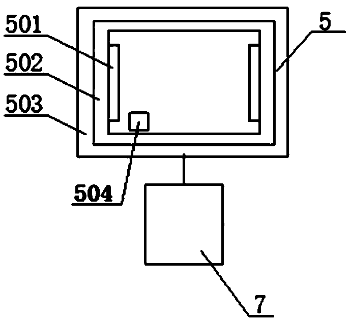
[0171] Such as figure 1 As shown, the on-site detection device includes a temperature adjustment mechanism 5 and an intelligent control unit 7 . The temperature adjustment mechanism 5, the temperature adjustment mechanism is configured to adjust the temperature rise and fall of the temperature compensation element of the gas density relay, so that the gas density relay generates a contact action and generates a contact signal; the intelligent control unit 7, It is connected with the temperature adjustment mechanism 5 and is configured to realize the control of the temperature adjustment mechanism 5; wherein, the contact signal includes alarm and / or lockout.

[0172] The temperature adjustment mechanism 5 of this embodiment is mainly composed of a heating element 501, a heat preservation piece 502, a controller 504, a temperature detector 3 (same as the temperature sensor), a temperature adjustment mechanism housing 503, and the like. The controller 504 may adopt PID control, ...

Embodiment 2

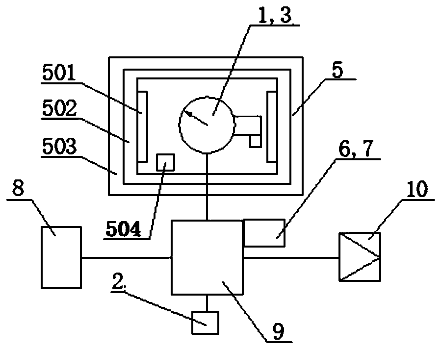
[0176] Such as figure 2 As shown, compared with the first embodiment, the on-site detection device of this embodiment adds a pressure sensor 2 , a temperature sensor 3 , an online verification contact signal sampling unit 6 , a multi-way joint 9 and an air supply interface 10 . The pressure sensor 2 and the air supply interface 10 are arranged on the multi-way joint 9 . The temperature adjustment mechanism 5 is arranged opposite to the gas density relay 1 , and the temperature sensor 3 is arranged in the casing of the density relay 1 . The gas density relay 1 and the gas supply interface 10 are set on the multi-way joint 9 , and the pressure sensor 2 , the online verification contact signal sampling unit 6 and the intelligent control unit 7 are set on the multi-way joint 9 . The temperature adjustment mechanism 5 is arranged outside the density relay 1 . Specifically, the density relay 1 communicates with the electrical equipment 8 through the multi-way joint 9; the pressur...

Embodiment 3

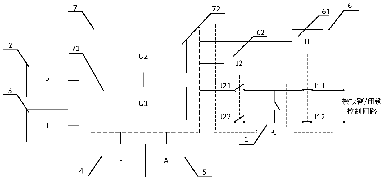
[0189] image 3 It is a schematic diagram of a control circuit of an on-site detection device.

[0190] The online verification contact signal sampling unit 6 mainly completes the sampling of the contact signal of the gas density relay 1 . That is, the basic requirements or functions of the on-line verification contact signal sampling unit 6 are: 1) It does not affect the safe operation of electrical equipment during verification, that is, when the contact of the gas density relay 1 moves during verification, it will not affect the electrical equipment. Safe operation of the equipment; 2) The contact signal control circuit of the gas density relay 1 does not affect the performance of the on-site detection device, especially the performance of the intelligent control unit 7, and does not cause damage to the on-site detection device or affect the test work.

[0191] Such as image 3 As shown, the online verification contact signal sampling unit 6 of this embodiment is mainly c...


PUM


Abstract

The invention provides a field detection device and system for achieving no maintenance of a gas density relay. The field detection device comprises a temperature regulation mechanism and an intelligent control unit, wherein the increase and decrease of the temperature of the temperature regulation mechanism are controlled by the intelligent control unit, thereby making the temperature of a temperature compensating component of the density relay rise and fall to complete the field detection of the gas density relay, and no maintainer is needed to operate on site to achieve no maintenance of the gas density relay and greatly improve the efficiency and reliable and safe running of power grids. The invention further provides a field detection method for supporting normal running of the fielddetection device.

Description

technical field [0001] The invention relates to the field of electric power technology, in particular to an on-site detection device, system and method for realizing maintenance-free gas density relays applied to high-voltage electrical equipment. Background technique [0002] Gas density relay is generally used to monitor and control the density of insulating gas in high-voltage and medium-voltage electrical equipment. It is equipped with a contact signal control circuit inside. When a gas leak occurs, the contact of the gas density relay will act to generate a contact signal, and the contact signal control circuit will send an alarm or block according to the contact signal, so as to realize the safe operation protection of electrical equipment. [0003] At present, SF6 (sulfur hexafluoride) electrical equipment has been widely used in the power sector and industrial and mining enterprises, which has promoted the rapid development of the power industry. In recent years, wi...

Claims


Application Information

Patent Timeline
Patent Type & Authority Applications(China)
IPC IPC(8): G01N9/00G01D21/02G05B19/042G01R31/327
CPCG01N9/00G01D21/02G05B19/0423G01R31/3272G01R31/3274G01R31/3271H01H33/563H01H35/26G01R31/3278G05B6/02
Inventor 常敏金海勇郭正操王乐乐曾伟廖海明
Owner SHANGHAI ROYE ELECTRICAL CO LTD
Why Eureka
Try Eureka