Direction-of-arrival measurement device and method based on large-scale antenna array

A large-scale antenna and measurement device technology, applied in the field of array antennas, can solve the problems of unbearable complexity of traditional algorithms, difficulty in realizing DOA estimation, and high complexity of data processing, so as to reduce measurement complexity, reduce measurement cost, and reduce antenna Quantity effect

Inactive Publication Date: 2019-11-05
XIAN UNIV OF SCI & TECH
View PDF9 Cites 0 Cited by
  • Summary
  • Abstract
  • Description
  • Claims
  • Application Information

AI Technical Summary

Problems solved by technology

However, most of the existing algorithms require one-dimensional or two-dimensional spectral search, and sometimes multi-dimensional nonlinear optimization is set, resulting in relatively high data processing complexity, and it is difficult to achieve real-time DOA estimation
[0004] For large-scale antenna array systems, the number of antennas is very large, and the complexity of traditional algorithms is unbearable
On the other hand, although there are low-complexity algorithms based on propagation operators, their estimation accuracy is low, and they are generally used for DOA estimation or scenarios that do not require high DOA estimation accuracy.

Method used


Image

  • Direction-of-arrival measurement device and method based on large-scale antenna array
  • Direction-of-arrival measurement device and method based on large-scale antenna array
  • Direction-of-arrival measurement device and method based on large-scale antenna array

Examples


Embodiment 1

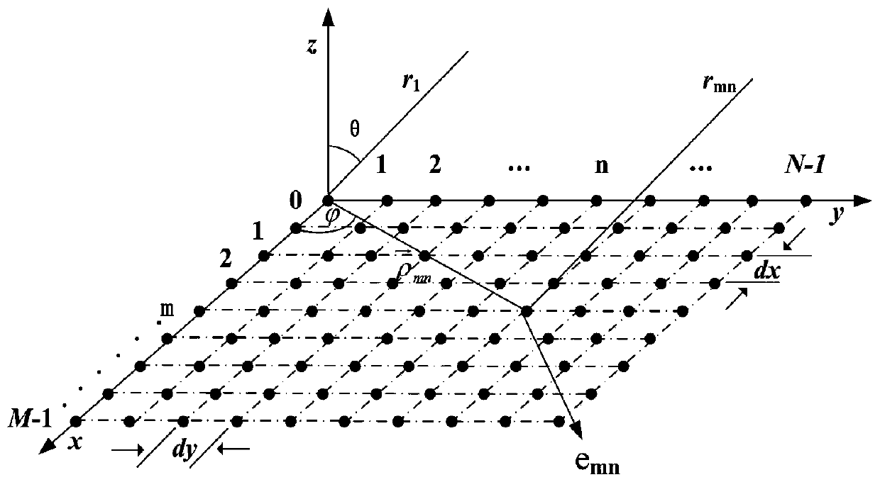
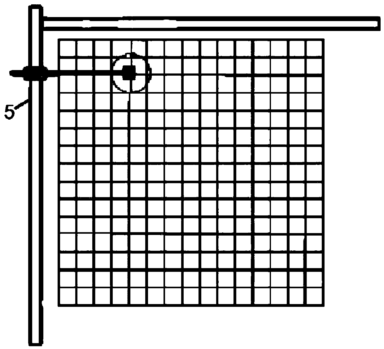
[0054] The sliders on the horizontal synchronous belt slide table and the vertical synchronous belt slide table are controlled by the stm32 single-chip microcomputer to be located at (x, y) positions, x=0,...,M; y=0,...,N,M,N Represents a positive integer.

[0055] Each time the stm32 single-chip microcomputer controls the movement distance of the slider to be less than or equal to half a wavelength (the wavelength with the measurement source), the phase difference of the incoming wave direction in the horizontal and vertical directions is obtained.
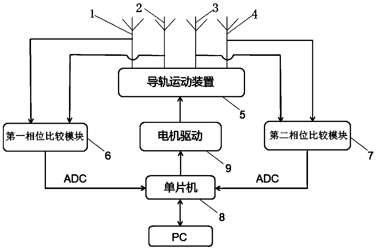
[0056] The voltage values ​​of the VPHS terminals (that is, the phase output terminals) of the two AD8302s are sampled by the stm32 microcontroller ADC.

[0057] In the microcontroller, by the formula y=3.4959e -7 x 3 -9.6342e -6 x 2 -0.0027307x+1.6882 for conversion between voltage and phase, x represents the voltage value of the VPHS terminals (ie, phase output terminals) of the two AD8302s sampled by the ADC of the stm32 s...

Embodiment 2

[0084] Single signal source measurement: M=N=8, the moving interval is half a wavelength, a single source is used, the frequency of the source is 2.554GHz, and the antenna uses a sleeve antenna to send signals. Carry out DOA estimation by the method provided by the present invention, and draw its actual measurement result in MATLAB, the result is as follows Figure 7 As shown, the azimuth angle of a single signal source is 160°, and the elevation angle is 36°. The measurement in the laboratory is not an ideal environment. There are reflections from metal objects in the laboratory and electromagnetic interference from the surrounding environment, resulting in other interference information.

Embodiment 3

[0086] Two signal sources are measured: M=N=16, the mobile interval is half a wavelength, two sources are adopted, and the single source in the second embodiment is separated by a power divider, as two source measurements, the frequency of the source is 2.554GHz, At the same time, the antenna uses a sleeve antenna for transmission, and the two antennas use 6dB and 10dB gain antennas respectively. Carry out DOA estimation by the method provided by the present invention, and draw its actual measurement result in MATLAB, the result is as follows Figure 8 As shown, one of the signal sources has an azimuth angle of 110° and an elevation angle of 12°, and the other signal source has an azimuth angle of 210° and an elevation angle of 12°. The measurement in the laboratory is not an ideal environment. There are reflections from metal objects in the laboratory and electromagnetic interference from the surrounding environment, resulting in other interference information.


PUM

PropertyMeasurementUnit
Pitch angleaaaaaaaaaa

Abstract

The invention discloses a direction-of-arrival measurement device and method based on a large-scale antenna array. The direction-of-arrival measurement device comprises a first receiving antenna, a second receiving antenna, a third receiving antenna and a fourth receiving antenna, wherein the first receiving antenna and the second receiving antenna are spaced transversely, the third receiving antenna and the fourth receiving antenna are spaced longitudinally, and the first receiving antenna, the second receiving antenna, the third receiving antenna and the fourth receiving antenna are installed on a guide rail movement device through a connecting device; the first receiving antenna and the second receiving antenna are both connected with the same first phase detection module, the third receiving antenna and the fourth receiving antenna are connected with the same second phase detection module, and a single-chip microcomputer is connected to the output ends of the first phase detectionmodule and the second phase detection module; a guide rail control unit and an upper computer are further connected to the single-chip microcomputer separately. According to the direction-of-arrival measurement device and method, the large-scale antenna array is simulated through a small number of antennas, and the antenna cost and computation complexity are lowered.

Description

【Technical field】 [0001] The invention belongs to the technical field of array antennas, in particular to a device and method for measuring the angle of arrival based on a large-scale antenna array. 【Background technique】 [0002] The wireless communication system develops very rapidly and has been widely used. The fifth-generation mobile communication system is entering commercial use, and related technologies have been extensively and deeply researched, and the measurement of large-scale antenna arrays is an important content that needs to be considered in practical applications. The angle of arrival (DOA) estimation is to use this characteristic of the antenna array to estimate the direction. Receive signals in different directions in space, and use estimation methods to perform fast and accurate calculations. The existing subspace spectrum estimation technology estimates the direction of arrival by using the characteristic that the signal arrives at different antennas ...

Claims


Application Information

Patent Timeline
IPC IPC(8): G01S3/32
CPCG01S3/32
Inventor 符渭波纪康康岳伟柳祎杨华张育芝
Owner XIAN UNIV OF SCI & TECH
Why Eureka
Try Eureka