
Control method suitable for intelligent load phase change

An intelligent, load-bearing technology, applied in the directions of reducing the asymmetry of the polyphase network, eliminating/reducing the asymmetry of the polyphase network, electrical components, etc. Unbalanced three-phase load distribution will not reduce low-voltage losses in the station area, so as to improve power quality problems, reduce damage to user electrical equipment, and improve customer satisfaction.

Pending Publication Date: 2019-11-05
SHANGHAI MUNICIPAL ELECTRIC POWER CO
View PDF0 Cites 3 Cited by
  • Summary
  • Abstract
  • Description
  • Claims
  • Application Information

AI Technical Summary

Problems solved by technology

The unbalanced three-phase load will increase the line loss of the station area, so that the unbalanced three-phase load in the distribution station area will have a negative impact on the power supply safety, power supply quality and economic operation of the distribution network, which is one of the main manifestations of the weak links of power distribution operation.
[0005] The SVG compensation leveling method belongs to the local compensation balance method, which only changes the transformer outlet voltage balance, but does not change the distribution state of the line load. The unbalanced three-phase load in the line is still serious, and because of its own large power consumption, so this type of Method balance will not reduce the low-voltage loss of the station area, but will increase the low-voltage loss of the station area; moreover, SVG only changes the voltage balance of the transformer outlet, but the three-phase three-phase load distribution is unbalanced, and the terminal voltage will still be very low, which cannot be reached at all. The purpose of improving terminal low voltage through three-phase load regulation

Method used


Image

  • Control method suitable for intelligent load phase change
  • Control method suitable for intelligent load phase change
  • Control method suitable for intelligent load phase change

Examples


Embodiment Construction

[0050] The present invention will be further described below in conjunction with the accompanying drawings and embodiments.

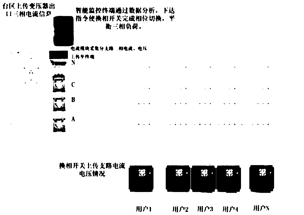
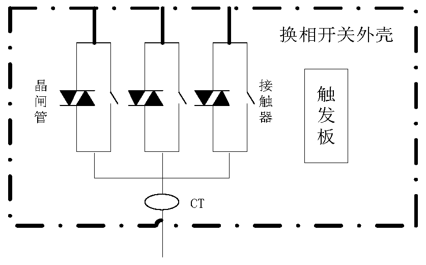
[0051] figure 2 Among them, the intelligent commutation switch is used to monitor the load current, voltage and phase of the meter box unit. The permanent magnet switch type commutation switch can perform fast phase switching through zero-crossing switching, and the switching time is within 5ms, truly realizing continuous power supply with load. switch. The intelligent commutation switch has the following functions:

[0052] 1) Mechanical interlock function:

[0053] The switch adopts a permanent magnet switch phase change switch to ensure that the phase change switch will not have a phase-to-phase short circuit accident under any circumstances;

[0054] 2) Standard switch mechanism:

[0055] With arc extinguishing mechanism, the arc extinguishing is fast, especially when the commutation time is less than 10ms, the advantages are more prominent. L...


PUM


Abstract

The invention discloses a control method suitable for intelligent load phase change, and belongs to the field of power supply control. The method comprises the following steps that: firstly, confirming one phase with the largest total current after each phase of total current is sorted as a default phase X; after a phase change command is received, according to the phase change command, switchingto a Y phase, and conducting a thyristor X on the default phase; then, disconnecting a contactor X on the default phase; disconnecting the thyristor X on the default phase; conducting a thyristor Y; closing the contactor X; disconnecting the thyristor Y; and therefore, finishing a phase change operation. The control method not only considers a three-phase unbalance degree index but also considersindexes, including voltage, reactive power and the like, and a court is under a stable state with a higher voltage percent of pass and a higher power factor. By use of the control method, a three-phase unbalance problem in the court can be effectively lowered, the loss of a distribution transformer is lowered, a situation that the electric equipment of a user is damaged is lowered, the operation noise of the court transformer is obviously lowered, and customer satisfaction degree is improved. The control method can be widely used for the control and regulation field of power grid operation quality.

Description

technical field [0001] The invention belongs to the field of power supply control, in particular to a control method for balancing loads in a power grid. Background technique [0002] Three-phase unbalance is an important indicator of power quality. Although there are many factors that affect the power system, the normal unbalance is mostly due to the asymmetry of three-phase components, line parameters or loads. The unbalanced three-phase load will increase the line loss of the station area, and the unbalanced three-phase load in the distribution station area will have a negative impact on the power supply safety, power supply quality and economic operation of the distribution network, which is one of the main manifestations of the weak links of power distribution operation. [0003] The unbalanced three-phase load will increase the line loss in the station area, reduce the output of the transformer, and damage the distribution network equipment. Therefore, it is an importa...

Claims


Application Information

Patent Timeline
IPC IPC(8): H02J3/26H02J13/00H02J3/24
CPCH02J3/26H02J3/24Y02E40/50
Inventor 唐海峰王颖韬唐海波刘均黄晓敏董培萌陈蓉蓉
Owner SHANGHAI MUNICIPAL ELECTRIC POWER CO
Learn More