
Element image rapid generation method of integrated imaging system

An elemental image and integrated imaging technology, applied in image communication, stereo system, electrical components, etc., can solve problems such as voids, slow calculation speed, complex equipment, etc., to avoid voids, solve stacking problems, improve generation speed and matching The effect of precision

Active Publication Date: 2019-11-05
CHANGCHUN UNIV OF SCI & TECH
View PDF6 Cites 0 Cited by
  • Summary
  • Abstract
  • Description
  • Claims
  • Application Information

AI Technical Summary

Problems solved by technology

Using microlens arrays or camera arrays to collect data has many problems such as complex equipment and signal crosstalk
The method of generating element images by computer needs to establish a 3D scene model, which is difficult to meet the needs of real-time display
In addition, the depth data collected by the depth camera and the scene color map can be used to generate element images. This method is to establish a function mapping from the 3D scene to the element image array, which is a many-to-one matching relationship, resulting in slow calculation speed and the element image There will be holes at the discontinuity of the corresponding scene depth, and the image quality of the element is low

Method used


Image

  • Element image rapid generation method of integrated imaging system
  • Element image rapid generation method of integrated imaging system
  • Element image rapid generation method of integrated imaging system

Examples


Embodiment Construction

[0034] The following will describe in detail the embodiment of "a method for quickly generating an elemental image array of an integrated imaging system" in conjunction with the accompanying drawings. In order to avoid too many unnecessary details, well-known structures or functions will not be described in detail in the following embodiments. Approximate language used in the following examples is for quantitative representations, indicating that certain variations in quantities are permissible without altering essential function. Unless defined otherwise, technical and scientific terms used in the following examples have the same meaning as commonly understood by one of ordinary skill in the art to which this invention belongs.

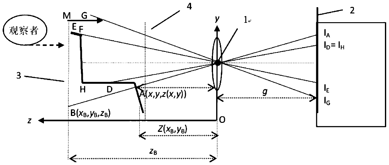
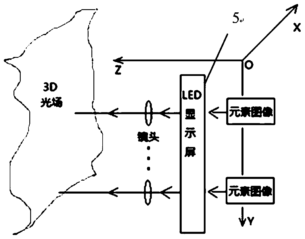
[0035] figure 2 Reproduce the schematic diagram of 3D light field for the present invention. According to equations (1) (2), the only and best matching point is searched along the optical path from each pixel of the element image to the scene. Th...


PUM


Abstract

The invention provides an element image rapid generation method for realizing integrated imaging display by using depth information and a scene 2D picture. According to an existing element image generation method, many-to-one mapping is established from a scene to an element image, and a large number of redundant calculations exist. According to the method, single-point mapping from the element image to the scene is established, each pixel in the element image only corresponds to a unique scene pixel, the matching precision is high, and holes at the depth step are eliminated. The time complexity of the method is mainly controlled by the sum of pixels of the element image array, the calculation and generation speed of the element image is more than 7 times that of other traditional methods,and the larger the total number of the pixels of the scene is, the more obvious the speed advantage of the method is.

Description

technical field [0001] The invention relates to an integrated imaging technology, in particular to a method for rapidly generating an element image array of an integrated imaging system. Background technique [0002] Integrated stereoscopic imaging is a stereoscopic display technology that reproduces 3D scenes through lens arrays. There are two main links: information collection of 3D scenes and stereoscopic light field reproduction. The elemental image array is one of the key factors affecting the quality of the reproduced light field. There are two main techniques for generating elemental image arrays, acquisition with optical devices and computer generation. Using microlens arrays or camera arrays to collect data has many problems such as complex equipment and signal crosstalk. The method of generating element images by computer needs to establish a 3D scene model, which is difficult to meet the needs of real-time display. In addition, the depth data collected by the d...

Claims


Application Information

Patent Timeline
IPC IPC(8): H04N13/128H04N13/275H04N13/302
CPCH04N13/128H04N13/275H04N13/302
Inventor 朴燕谷岳佳楠王宇
Owner CHANGCHUN UNIV OF SCI & TECH
Learn More