Method and special equipment for treating slag in smelting process of blast furnace or submerged arc furnace

A technology for smelting process and treatment equipment, which is applied in separation methods, chemical instruments and methods, filtration and separation, etc. It can solve the problems of increasing system cost and maintenance workload, high water content of slag-water mixture, and large slag content in filtered water quality. , to prolong the service life of the equipment, improve the conveying capacity and efficiency, and achieve good water filtration effect

Active Publication Date: 2019-11-08
付光明
View PDF3 Cites 1 Cited by
  • Summary
  • Abstract
  • Description
  • Claims
  • Application Information

AI Technical Summary

Problems solved by technology

For example: the bottom filtration process is that the blast furnace or submerged arc furnace slag is granulated by high-pressure water, enters the slag ditch, enters the slag pool from the slag ditch, filters or settles in the slag pool, and drives the grab to filter or settle the slag The slag is transported to other locations. The bottom filtration method has problems such as high engineering investment, large floor area, and easy compaction of the slag pool.
The Tula method process is that the blast furnace or submerged arc furnace slag is granulated by high-pressure water, then enters the slag flushing ditch, then enters the slag feeding chute from the slag flushing ditch, and then enters the rotary filter. The slag-water mixture is dehydrated in the rotary filter. The top of the rotary filter falls into the slag discharge chute, then enters the belt conveyor, and is transported to the designated place by the belt conveyor. The water and fine slag filtered out at the bottom of the rotary filter return to the pool of the pump station through the slag water conveying pipeline; Lhasa method, The slag treatment methods such as the Yinba method and the Tula method have problems such as high engineering investment, large slag content in filtered water quality, and high failure rate.
The important reasons for the above problems are: first, there is no water filtration behind the slag flushing ditch, so that the water content of the slag-water mixture is too high; second, the filter screen of the rotary filter is made of stainless steel, and the fine slag will pass through the filter screen Entering the return water pipeline, resulting in poor water filtration effect, unable to guarantee the filtered water quality, and the residual hot water will not be directly used for heating and power generation
In addition, since the filtered water contains impurities, the water pumps and pipelines in the system are all wear-resistant pipelines and wear-resistant water pumps, which increases the cost and maintenance workload of the system

Method used


Image

  • Method and special equipment for treating slag in smelting process of blast furnace or submerged arc furnace
  • Method and special equipment for treating slag in smelting process of blast furnace or submerged arc furnace
  • Method and special equipment for treating slag in smelting process of blast furnace or submerged arc furnace

Examples


Embodiment 1

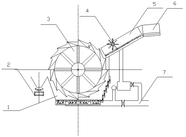
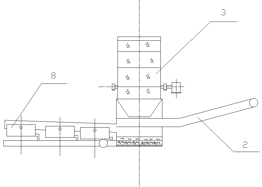
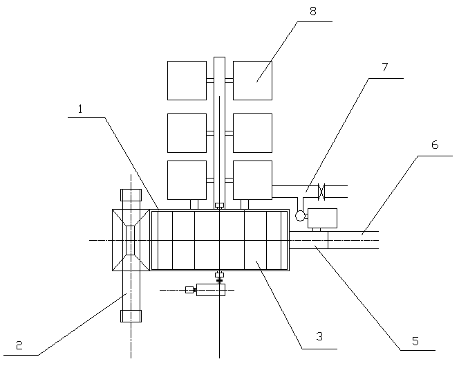
[0058] Embodiment 1: There are helical blades 27 on both sides of the central shaft, and several shifting teeth are arranged in the middle; the helical blades 27 on both sides rotate in opposite directions to convey materials to the center; the discharge port 28 is on the central axis of the shell with the upper opening groove , when the width of the discharge opening is smaller than the width of the opening groove on the shell, structure one is applicable.

Embodiment 2

[0059] Embodiment 2: The slag remover 10 is composed of a number of pulling teeth installed on the central shaft, without helical blades; the discharge port 28 is on the central axis of the shell with an upper opening groove, and the width of the discharge port is greater than or equal to the upper opening of the shell When the notch width of the groove type is used, the second structure is applicable.

Embodiment 3

[0060] Embodiment 3: All screw blades are installed on the central shaft to convey materials to one side; the discharge port 28 is arranged on the side of the shell, which is suitable for structure 3.

[0061] The shell 9 is a channel-shaped steel structure, and can also be made of reinforced concrete into a channel-shaped structure.

[0062] Between the filter screen two 14 and the filter screen 25 and between the filter screen 25 and the bottom of the housing 9, criss-cross steel partitions 23 are arranged, and the space between the filter screen two 14 and the filter screen 25 and the filter screen The space between 25 and the bottom of the housing 9 is divided into a plurality of grids, and filter stones 13 are arranged in the grids; holes 24 are arranged on the criss-cross steel partitions, and the holes 24 communicate with the exhaust pipe 15 outside the housing.

[0063] The top of the filter screen two 14 is provided with a plurality of vertically arranged front baffle...


PUM


Abstract

The invention relates to a method and special equipment for treating slag in the smelting process of a blast furnace or a submerged arc furnace, belonging to the technical field of slag treatment of the blast furnace or submerged arc furnace. A water filter is arranged between granulation equipment and slag treatment equipment; a shell (9) has a groove profile with an upper opening, and a feedingport (29) and a discharging port (28) of the shell (9) are respectively connected with the granulation equipment and slag treatment equipment; at least one layer of filter screen (25) is arranged at the bottom of the shell (9), and filter stones (13) are arranged on the filter screen (25). The special equipment has the beneficial effects that the water quantity entering the slag treatment equipment is reduced, the water filtering effect is good, the conveying capacity and efficiency of the slag treatment equipment are improved, the abrasion to the equipment is reduced, and the service life ofthe equipment is prolonged; the filtered water quality is ensured, wear-resistant pipelines and slurry pumps are not required, equipment investment and failure rate are greatly reduced, and residual hot water can be used for power generation and heating.

Description

technical field [0001] The invention relates to a processing method and special processing equipment for molten slag in the blast furnace or submerged arc furnace smelting process. The molten slag produced in the blast furnace or submerged arc furnace and other metal smelting processes is subjected to high-pressure water quenching and granulation, and the slag-water mixture is separated. The invention belongs to the technical field of blast furnace or submerged arc furnace slag treatment. Background technique [0002] At present, in the field of metal smelting, many blast furnace or submerged arc furnace slag treatment technologies have been used, including: bottom filtration method, Lhasa method, Yinba method, Tula method, etc. These slag treatment technologies exist to varying degrees some problems. For example: the process flow of the bottom filtration method is that the blast furnace or submerged arc furnace slag is granulated by high-pressure water, enters the slag dit...

Claims


Application Information

Patent Timeline
Patent Type & Authority Applications(China)
IPC IPC(8): C04B5/00B01D36/02
CPCC04B5/00B01D36/02Y02W30/50
Inventor 付光明
Owner 付光明
Why Eureka
Try Eureka