
Noise elimination and reduction device of diesel engine

A diesel engine and noise reduction technology, which is applied to the muffler device, exhaust device, engine cooling and other directions, can solve the problems of reducing the temperature of the exhaust pipe, inconvenient exhaust pipe placement, reducing the vibration amplitude of the diesel engine, etc., so as to reduce the impact force. , the effect of lowering the temperature and adjusting the height

Active Publication Date: 2019-11-08
广东宇豪新材料科技有限公司
View PDF7 Cites 4 Cited by
  • Summary
  • Abstract
  • Description
  • Claims
  • Application Information

AI Technical Summary

Problems solved by technology

[0003] For the use of agricultural machinery, diesel engines are often used as power. When the diesel engine is working, it will produce a lot of noise. Generally, the noise reduction device is used to reduce the noise of the diesel engine. However, there is an existing noise reduction device for diesel engines. The following defects: It is not conducive to squeezing and fixing the diesel engine, the tightness of the clamping is not easy to adjust, and it is not conducive to reducing the vibration amplitude of the diesel engine, the stability is poor, and it is not conducive to noise reduction; it is not conducive to reducing the temperature of the exhaust pipe and reducing noise. The noise reduction effect is poor; it is not conducive to adjusting the height of the semicircular storage plate, and it is not convenient to match the placement of the exhaust pipe; in view of this defect, it is necessary for us to design a noise reduction device for diesel engines

Method used


Image

  • Noise elimination and reduction device of diesel engine
  • Noise elimination and reduction device of diesel engine
  • Noise elimination and reduction device of diesel engine

Examples


Embodiment Construction

[0034] The technical solutions of the present invention will be clearly and completely described below in conjunction with the embodiments. Apparently, the described embodiments are only some of the embodiments of the present invention, not all of them. Based on the embodiments of the present invention, all other embodiments obtained by persons of ordinary skill in the art without creative efforts fall within the protection scope of the present invention.

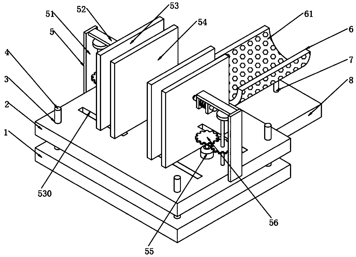
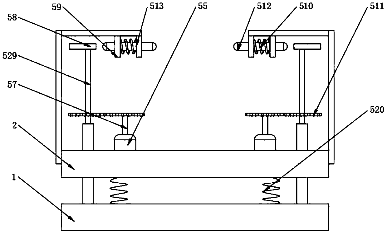
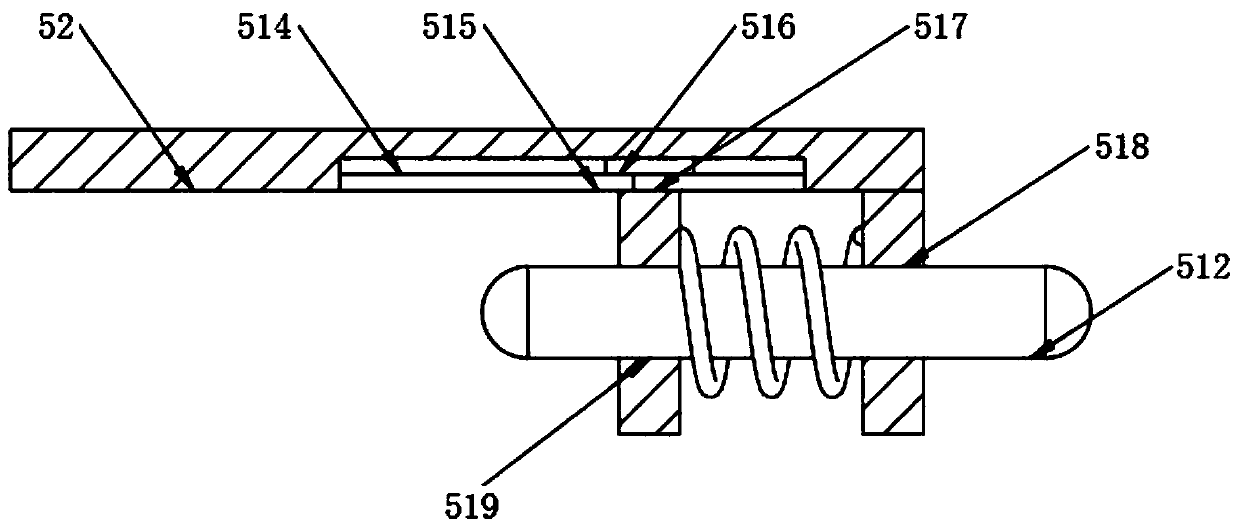
[0035] Such as Figure 1-9 As shown, a noise reduction device for a diesel engine includes a lower base 1, an upper base 2, a fixing hole 3, a fixing rod 4, an extruding assembly 5, a cooling assembly 6, a lifting assembly 7 and a fixing plate 8, and the lower base 1 The top of the top is welded and fixed with fixed rods 4 around, and the top of the upper base 2 is provided with fixed holes 3 around the top, and the fixed holes 3 penetrate to the bottom of the upper base 2, and the upper base 2 is sleeved on the outside of ...


PUM


Abstract

The invention discloses a noise elimination and reduction device of a diesel engine. The noise elimination and reduction device comprises a lower base, an upper base, fixed holes, fixed rods, an extrusion assembly, a cooling assembly, a lifting assembly and a fixed plate, wherein the fixed rods are fixedly welded to the periphery of the top of the lower base; the fixed holes are formed in the periphery of the top of the upper base, and the fixed holes penetrate to the bottom of the upper base; the upper base sleeves the fixed rods through the fixed holes; the upper base is provided with the extrusion assembly; and one side of the lower base is provided with the fixed plate. According to the noise elimination and reduction device, the diesel engine can be convenient to extrude and fix, andthe distance between an extrusion plate a and an extrusion plate b is adjusted conveniently, so that the extrusion tightness is adjusted, the vibration amplitude of the diesel engine is reduced, the stability is improved, and the noise reduction and elimination are achieved conveniently; the temperature of an exhaust pipe can be reduced, and the impact force between molecules is reduced, so that the noise reduction and elimination are achieved conveniently; and the height of a semicircular storage plate can be adjusted conveniently, and the exhaust pipe can be placed conveniently.

Description

technical field [0001] The invention relates to the field of diesel engine noise reduction equipment, in particular to a diesel engine noise reduction device. Background technique [0002] A diesel engine is an engine that burns diesel for energy release. It was invented by German inventor Rudolf Diesel (Rudolf Diesel) in 1892. To commemorate the inventor, diesel is represented by his surname Diesel, and the diesel engine is also called Diesel engine ( Diesel engine). Diesel engines are widely used and are at the core of the industrial chain. In the past ten years of development, the diesel engine production industry has formed a series of supporting enterprises, and many diesel engine enterprises have played the role of general contractor and assembler. Some key parts of diesel engines: crank connecting rod , Pistons, cylinder liners, and cams have been handed over to professional companies for production. Specialized division of labor enables diesel engine manufacturer...

Claims


Application Information

Patent Timeline
IPC IPC(8): F02B77/00F16F15/04F01P9/06F01N3/04
CPCF01N3/043F01P9/06F02B77/00F16F15/04
Inventor 孙从贵杭霖生陆继忠
Owner 广东宇豪新材料科技有限公司
Learn More