Anti-aging hydraulic oil cylinder with high transmission efficiency

A transmission efficiency, hydraulic cylinder technology, applied in the field of hydraulic machinery, can solve the problems of increasing leakage, destroying transmission accuracy, reducing the practicability of hydraulic cylinders, etc., and achieving the effects of preventing aging, ensuring transmission efficiency, and improving practicability

Inactive Publication Date: 2019-11-08
JIANGSU XINLIAN HYDRAULIC MECHANICAL & ELECTRICALCO
View PDF0 Cites 2 Cited by
  • Summary
  • Abstract
  • Description
  • Claims
  • Application Information

AI Technical Summary

Problems solved by technology

[0003] The main medium for the movement of the hydraulic cylinder is hydraulic oil. When the hydraulic cylinder is running, the piston seal moves along the inside of the cylinder to generate friction, which makes the temperature of the hydraulic oil gradually rise. When the hydraulic cylinder reciprocates, the temperature of the hydraulic oil rises. The speed is faster, and the existing hydraulic rod cannot quickly cool down and dissipate the hydraulic oil, resulting in a continuous rise in the temperature of the hydraulic oil, which will not only significantly reduce the viscosity of the oil, increase leakage, age the components, and destroy the oil film of the sliding parts. The wear of the oil components will be aggravated, and when the temperature is higher, the phenomenon of jamming will also occur, which will damage the transmission accuracy and affect the transmission efficiency, which will lead to the reduction of the practicability of the existing hydraulic cylinder

Method used


Image

  • Anti-aging hydraulic oil cylinder with high transmission efficiency
  • Anti-aging hydraulic oil cylinder with high transmission efficiency
  • Anti-aging hydraulic oil cylinder with high transmission efficiency

Examples


Embodiment Construction

[0026] The present invention is described in further detail now in conjunction with accompanying drawing. These drawings are all simplified schematic diagrams, which only illustrate the basic structure of the present invention in a schematic manner, so they only show the configurations related to the present invention.

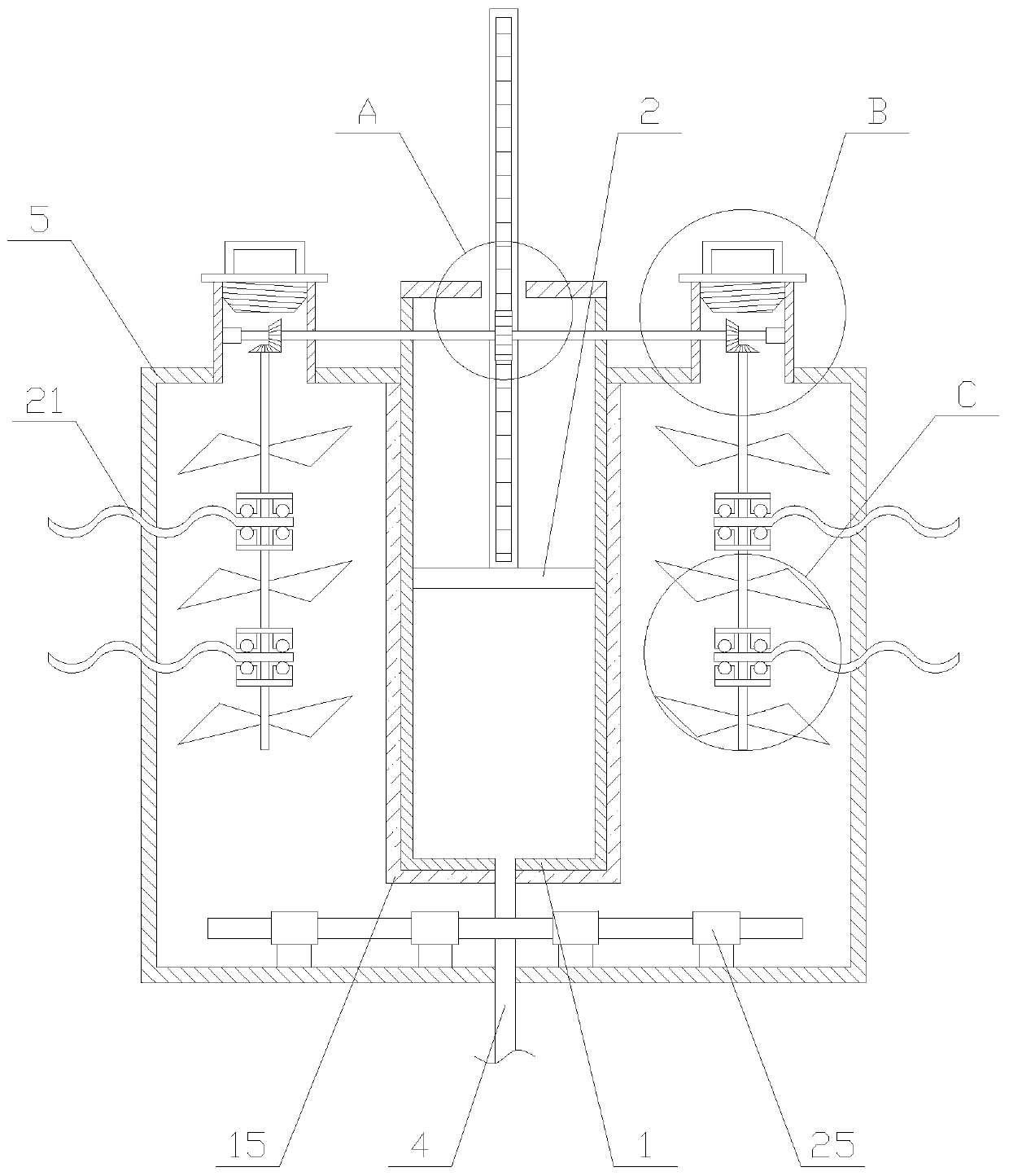
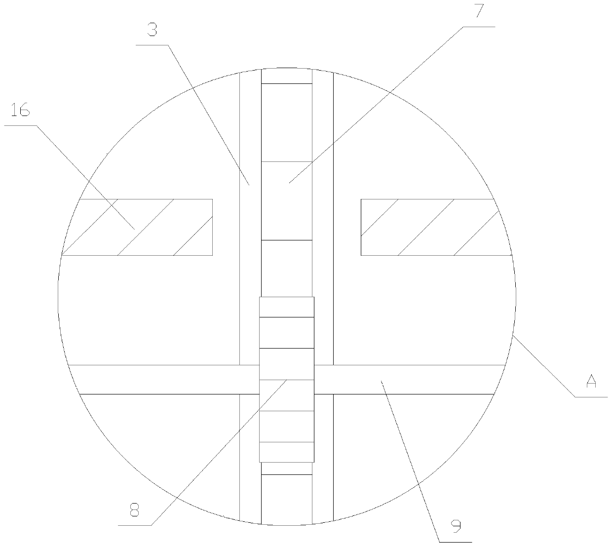
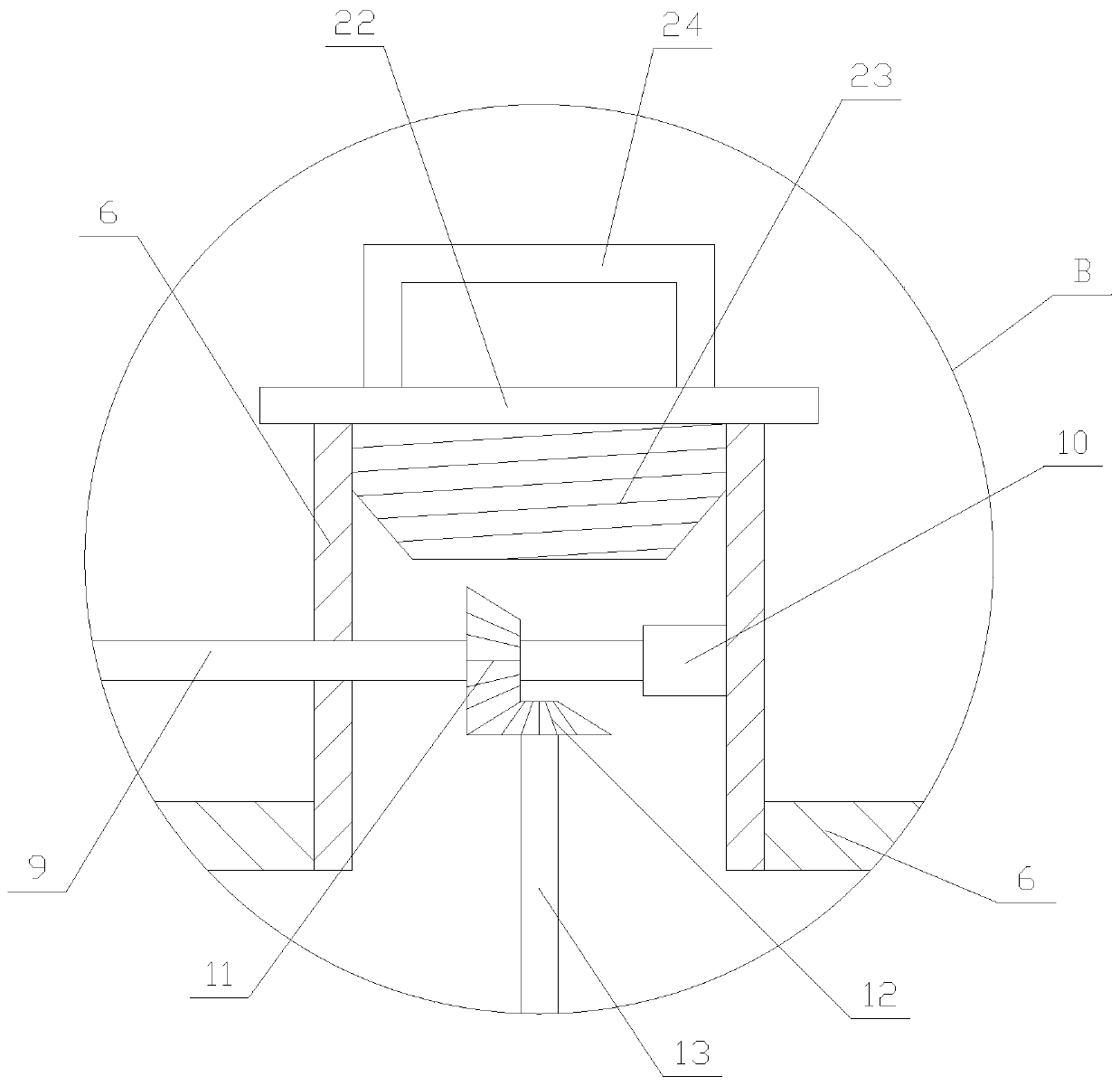
[0027] like figure 1 As shown, an anti-aging hydraulic cylinder with high transmission efficiency includes a cylinder body 1, a sealing plate 2, a piston rod 3, an oil pipe 4, a water tank 5, a cooling mechanism and two water injection pipes 6, and the outer periphery of the sealing plate 2 It is sealed and connected with the inner wall of the cylinder body 1, the piston rod 3 is fixed on the sealing plate 2, a gap is provided above the water tank 5, and the outer periphery of the upper part of the cylinder body 1 is fixedly connected with the inner wall of the gap. The body 1 is located between two water injection pipes 6, the end of the water injection pipe...


PUM


Abstract

The invention relates to an anti-aging hydraulic oil cylinder with high transmission efficiency, and the anti-aging hydraulic oil cylinder comprises a cylinder body, a sealing plate, a piston rod, anoil pipe, a water tank, a cooling mechanism and two water injection pipes, wherein the cooling mechanism comprises a transmission assembly and two cooling assemblies, the transmission assembly comprises a rack, a circular gear, a transmission shaft and two bearings, and the cooling assembly comprises a driving bevel gear, a driven bevel gear, a rotating shaft, a plurality of rotary vanes and a plurality of supporting units. The anti-aging hydraulic oil cylinder with high transmission efficiency absorbs the heat of the cylinder body through a water solution in the water tank to achieve the purpose of cooling the hydraulic oil, the transmission assembly acts on heating assemblies at two sides to enable the rotary vanes to rotate to drive water flow to flow, the heat is conveniently diffusedin the water solution and is transmitted to the outside after the heat is absorbed by a heat conducting plate, the water solution continuously cools the hydraulic oil, thereby ensuring the transmission efficiency of the hydraulic cylinder, and the equipment is prevented from aging, and therefore the practicability of the equipment is improved.

Description

technical field [0001] The invention relates to the field of hydraulic machinery, in particular to an anti-aging hydraulic oil cylinder with high transmission efficiency. Background technique [0002] A hydraulic cylinder is a hydraulic actuator that converts hydraulic energy into mechanical energy and performs linear reciprocating or oscillating motion. Its structure is reliable and its work is reliable. When it is used to realize reciprocating motion, the deceleration device can be eliminated, and there is no transmission gap, and the movement is stable. Therefore, it is widely used in various mechanical hydraulic systems. [0003] The main medium for the movement of the hydraulic cylinder is hydraulic oil. When the hydraulic cylinder is running, the piston seal moves along the inside of the cylinder to generate friction, which makes the temperature of the hydraulic oil gradually rise. When the hydraulic cylinder reciprocates, the temperature of the hydraulic oil rises. T...

Claims


Application Information

Patent Timeline
Patent Type & Authority Applications(China)
IPC IPC(8): F15B15/14F15B21/042
CPCF15B15/14F15B21/0423F15B2211/62
Inventor 高连信李伟
Owner JIANGSU XINLIAN HYDRAULIC MECHANICAL & ELECTRICALCO
Why Eureka
Try Eureka