Angle type porous medium burner

A technology of porous media and burners, applied in the direction of burners, gas fuel burners, combustion types, etc., can solve the problems of burner backfire and defire instability, etc., to broaden the limit range of flame stability speed and improve outlet radiation Efficiency, the effect of preventing flame flashback and defiring

Active Publication Date: 2019-11-08
NORTHEASTERN UNIV
View PDF5 Cites 4 Cited by
  • Summary
  • Abstract
  • Description
  • Claims
  • Application Information

AI Technical Summary

Problems solved by technology

[0006] Aiming at the deficiencies in the prior art, the present invention provides an angular porous media burner, which can effectively solve the unstable pro...

Method used


Image

  • Angle type porous medium burner
  • Angle type porous medium burner
  • Angle type porous medium burner

Examples


Embodiment Construction

[0022] In order to better explain the present invention and facilitate understanding, the technical solutions and effects of the present invention will be described in detail below through specific implementation manners in conjunction with the accompanying drawings.

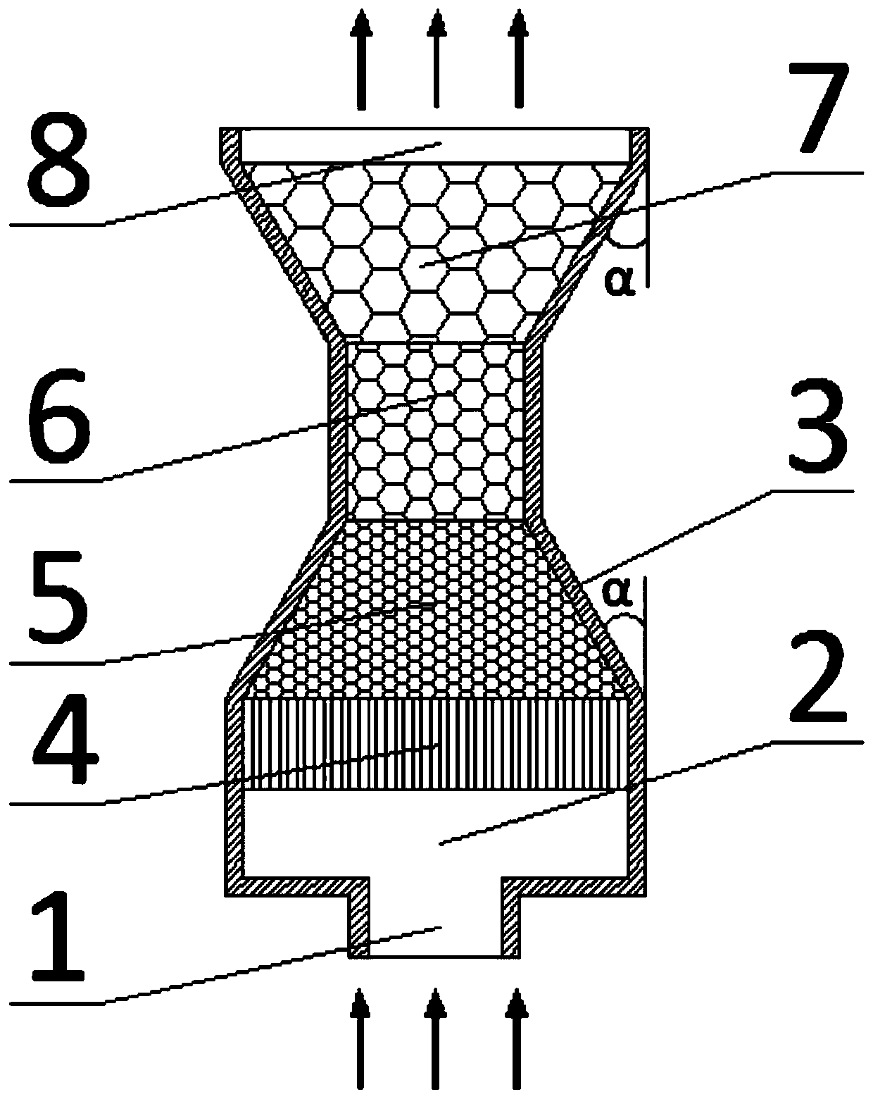
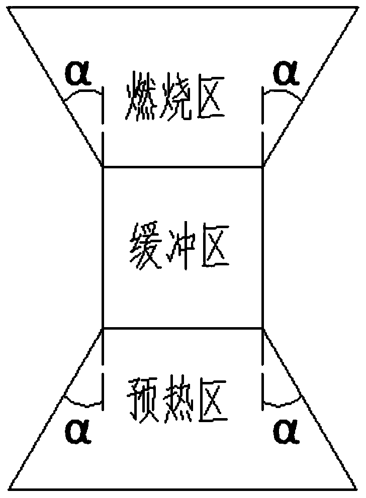
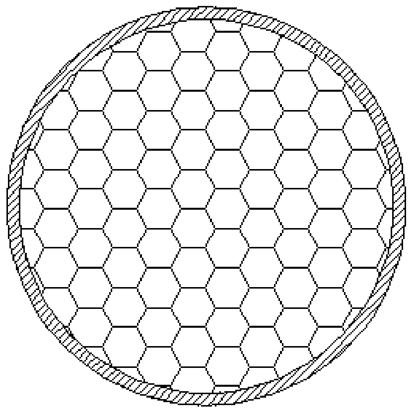
[0023] like Figure 1-3 As shown, an angle-shaped porous media burner is composed of gas inlet 1, combustion front chamber 2, protection zone 4, preheating zone 5, buffer zone 6, combustion zone 7 and flue gas outlet 8, surrounded by burner The casing 3 is closed, and the burner casing 3 is made of thermal insulation material. The preheating zone 5, the buffer zone 6, and the combustion zone 7 are collectively referred to as the porous medium zone. In the multi-media zone, the preheating zone 5 and the combustion zone 7 are funnel-shaped. , respectively set at both ends of the buffer zone 6, the preheating zone 5 and the combustion zone 7 are symmetrical about the center of the buffer zone 6. The protection are...


PUM

PropertyMeasurementUnit
Hole densityaaaaaaaaaa

Abstract

The invention relates to an angle type porous medium burner. The angle type porous medium burner comprises a gas inlet, a combustion front chamber, a burner shell, a protection zone, a preheating zone, a buffer zone, a combustion zone and a flue gas outlet; the preheating zone, the buffer zone and the combustion zone are collectively called as porous medium zones and are filled with porous mediummaterials; and the preheating zone and the combustion zone are respectively and gradually expanded inwards and outwards by a certain angle alpha, and meanwhile, the buffer zone is arranged in the preheating zone and the combustion zone, so that the air flow speed is reduced, and the flame inclination phenomenon is prevented. The limit range of the flame stabilizing speed can be obviously widened,flame tempering and fire dropping are effectively prevented, the outlet radiation efficiency is improved, and meanwhile, the occurrence of thermal shock damage of the porous medium is reduced.

Description

technical field [0001] The invention belongs to the technical field of burners, in particular to an angular porous media burner. Background technique [0002] In recent years, with the rapid development of China's economy, energy and environmental issues have increasingly become the focus of attention. Our country is currently facing the dilemma of the continuous reduction of fossil fuels and the increasing environmental pollution. Therefore, in order to establish a sustainable economic model, improve the energy structure, improve the energy consumption mode, and improve the effective utilization of energy, we must make full use of industrial production and energy. Various low calorific value gases in production realize efficient and clean utilization of conventional energy. The combustible components of low-calorific-value gas are thin, and it is difficult to effectively use conventional combustion technology. How to realize the effective combustion of this kind of gas and...

Claims


Application Information

Patent Timeline
IPC IPC(8): F23D14/14F23D14/66F23D14/74F23D14/82
CPCF23D14/14F23D14/66F23D14/74F23D14/82Y02E20/34
Inventor 刘慧康刘胜宋雯煜薛原郜晓晖
Owner NORTHEASTERN UNIV
Why Eureka
Try Eureka