Supercharge Your Innovation With Domain-Expert AI Agents!

Flue gas sampling device and method for power plant

A flue gas sampling and power plant technology, applied in the direction of sampling devices, sampling, measuring devices, etc., can solve the problems of corrosion of the detection part and the failure of the detection part to continue to use, so as to reduce the degree of damage, facilitate the detection requirements, and have strong practicability Effect

Inactive Publication Date: 2019-11-08
NANJING CHONON ENERGY SAVING TECH
View PDF0 Cites 3 Cited by
  • Summary
  • Abstract
  • Description
  • Claims
  • Application Information

AI Technical Summary

Problems solved by technology

[0003] Since the flue gas of the power plant is the exhaust gas produced by burning various combustibles, the flue gas will contain various corrosive gases such as hydrogen sulfide. The existing sampling device is directly sampling, and each sampling will cause corrosion to the detection part. , after multiple samplings, the detection part will not be able to continue to be used. In view of this disadvantage, a sampling device that can reduce the corrosion performance of flue gas is now provided

Method used


Image

  • Flue gas sampling device and method for power plant
  • Flue gas sampling device and method for power plant
  • Flue gas sampling device and method for power plant

Examples


Embodiment 1

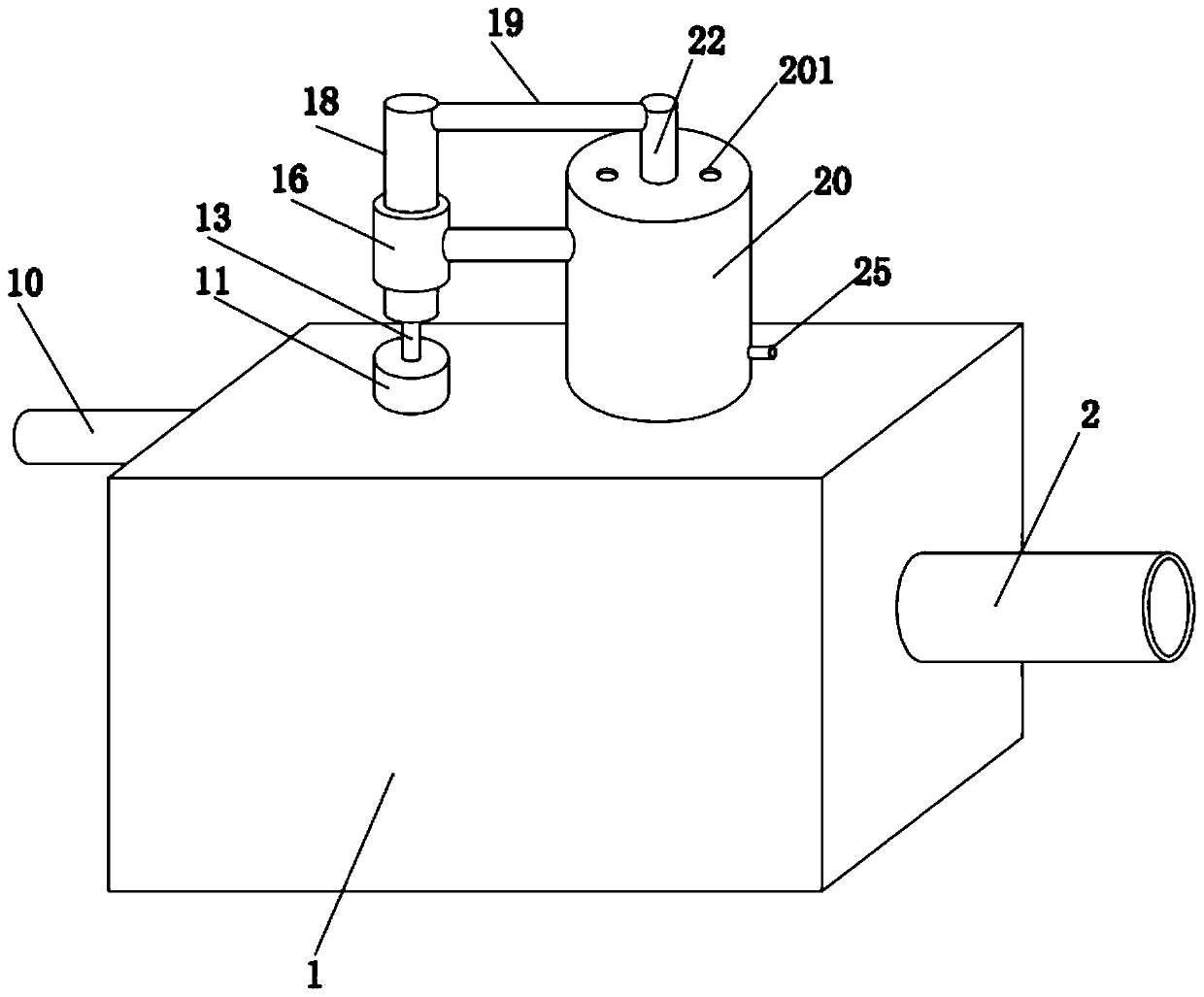
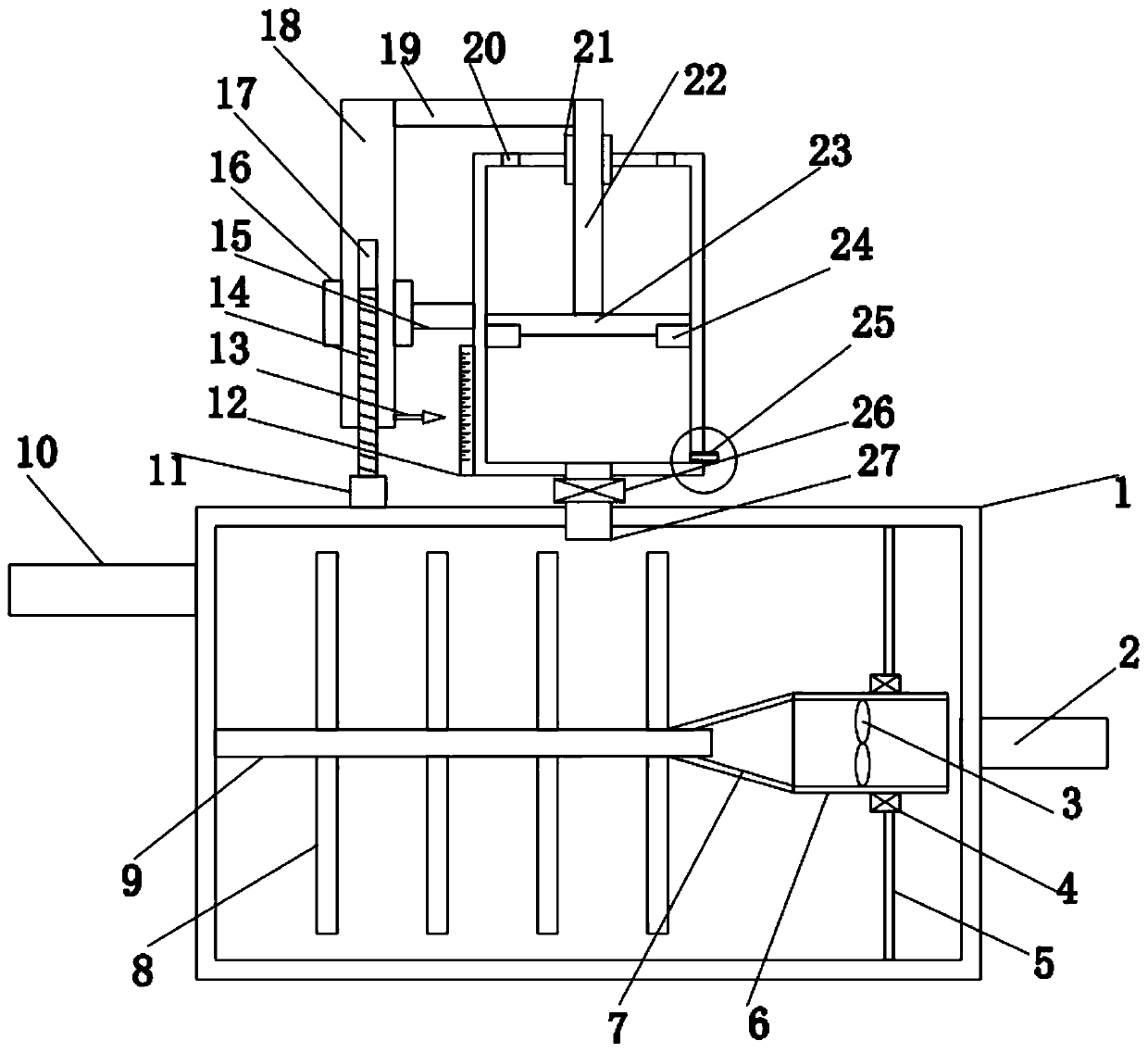
[0033] see Figure 1-3 , in an embodiment of the present invention, a flue gas sampling device for a power plant includes a buffer box 1 for buffering flue gas and an air inlet pipe 2 arranged at its inlet end, and the outlet end of the buffer box 1 is provided with a Exhaust air outlet pipe 10, the buffer box 1 is also provided with a mixing part and a piston part;

[0034] The mixing part is used to stir the gas inside the buffer box 1 evenly, so as to improve the accuracy of later detection;

[0035] The mixing part includes a fixed rotating shaft 9 whose left end is rotatably connected to the inner wall on the left side of the buffer box 1. The fixed rotating shaft 9 is coaxially arranged with the air intake pipe 2. Several stirring blades 8 are symmetrically arranged on the upper and lower sides of the fixed rotating shaft 9. , the right end of the fixed rotating shaft 9 is coaxially provided with an air guiding cylinder 6, the left end of the air guiding cylinder 6 is c...

Embodiment 2

[0045] see Figure 4 , in order to further improve the gas mixing effect, the stirring blade 8 is arranged in a rectangular shape, and at least one air guide cone hole 81 is arranged on the windward surface thereof, and the inner end of the air guide cone hole 81 communicates with the exhaust gas arranged at the end of the stirring blade 8 Passage 82, when stirring blade 8 rotates, the air on its windward side will enter along the air guide cone 81, and then be discharged from the exhaust passage 81, thereby generating an outward air flow, thereby further improving the mixing effect. Effect.

Embodiment 3

[0047] In order to improve the power gain value of the power fan blade 3, the structure of the air guide cylinder 6 is a conical tube with a large left end and a small right end, so that the air flow rate passing through the power fan blade 3 can be increased, and then it can obtain greater power. value.


PUM


Abstract

The invention discloses a flue gas sampling device and method for a power plant. The device comprises a caching box for caching flue gas and an air inlet tube arranged at an air inlet end. An air outlet pipe for air exhausting is arranged at an air outlet end of the caching box. A mixing part and a piston part are also arranged at the caching box; the mixing part is used for stirring gas in the caching box uniformly to improve accuracy of post-stage detection. On the basis of improvement of defects of the existing device, with the mixing part, the gas uniformity is improved and thus the detection accuracy is improved; with the piston part, the gas is compressed or expands, so that the gas concentration is increased or decreased; the detection precision is improved when the concentration increases; the damage degree of the detector in detection is reduced when the concentration decreases and thus the service life is prolonged. Therefore, the actual detection demand is satisfied and thepracticability is high.

Description

technical field [0001] The invention relates to the field of power plant flue gas temperature measuring devices, in particular to a flue gas sampling device and method for power plants. Background technique [0002] A power plant is a factory that uses combustibles (such as coal) as fuel to produce electricity. When the fuel is burned, the water is heated to generate steam, which converts the chemical energy of the fuel into thermal energy. The steam pressure drives the steam turbine to rotate, and the thermal energy is converted into mechanical energy. Then the steam turbine drives the generator to rotate, and the mechanical energy is converted into electrical energy. According to the standard, the flue gas in the chimney of the power plant is generally sampled and monitored. In the prior art, the flue gas sampling device is generally used for sampling. The flue gas sampling device mainly includes a sample storage box, a gas transmission pipe connected to the sample storag...

Claims


Application Information

Patent Timeline
Patent Type & Authority Applications(China)
IPC IPC(8): G01N1/22G01N1/38
CPCG01N1/2258G01N1/38G01N2001/386
Inventor 周惠
Owner NANJING CHONON ENERGY SAVING TECH
Features
  • R&D
  • Intellectual Property
  • Life Sciences
  • Materials
  • Tech Scout
  • Unparalleled Data Quality
  • Higher Quality Content
  • 60% Fewer Hallucinations
Learn More