
Electroluminescence device and its manufacturing method and application

A technology of electroluminescent devices and manufacturing methods, which is applied in the direction of electric solid-state devices, semiconductor/solid-state device manufacturing, electrical components, etc., and can solve problems such as poor conductivity and unfavorable performance improvement of display panels, so as to improve performance and improve electrical connection effects Effect

Active Publication Date: 2022-02-11
GUANGDONG JUHUA PRINTING DISPLAY TECH CO LTD
View PDF4 Cites 0 Cited by
  • Summary
  • Abstract
  • Description
  • Claims
  • Application Information

AI Technical Summary

Problems solved by technology

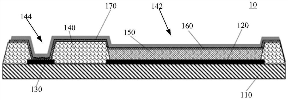
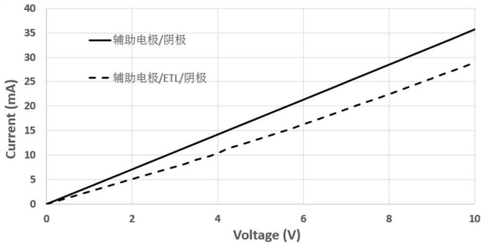
However, when the organic functional layer is prepared by the open mask method, a layer of organic functional layer will be deposited in the connection hole between the auxiliary electrode and the top transparent electrode. Since the organic functional layer such as ETL is a semiconductor material with poor conductivity, a voltage will be generated here drop, which is not conducive to the performance improvement of the display panel

Method used


Image

  • Electroluminescence device and its manufacturing method and application
  • Electroluminescence device and its manufacturing method and application
  • Electroluminescence device and its manufacturing method and application

Examples


Embodiment Construction

[0034] In order to facilitate the understanding of the present invention, the present invention will be described more fully below with reference to the associated drawings. Preferred embodiments of the invention are shown in the accompanying drawings. However, the present invention can be embodied in many different forms and is not limited to the embodiments described herein. On the contrary, these embodiments are provided to make the understanding of the disclosure of the present invention more thorough and comprehensive.

[0035] It should be noted that when an element is referred to as being “disposed on” another element, it may be directly on the other element or there may also be an intervening element. When an element is referred to as being "connected to" another element, it can be directly connected to the other element or intervening elements may also be present.

[0036] Unless otherwise defined, all technical and scientific terms used herein have the same meaning...


PUM

PropertyMeasurementUnit
thicknessaaaaaaaaaa

Abstract

The present invention relates to an electroluminescent device and its manufacturing method and application. The electroluminescent device includes a substrate, a pixel electrode layer, an auxiliary electrode layer, a pixel defining layer, a light-emitting layer, an organic functional layer and a transparent cathode layer. The electroluminescent device carbonizes and burns through the organic functional layer between the auxiliary electrode layer and the transparent cathode layer. For example, the organic functional layer of the semiconductor material is carbonized or rearranged to form discontinuities. Therefore, an effective direct contact can be formed between the auxiliary electrode layer and the transparent cathode layer, which is beneficial to improve the electrical connection effect between the auxiliary electrode layer and the transparent cathode layer, thereby improving the performance of the electroluminescent device.

Description

technical field [0001] The invention relates to the technical field of electroluminescence, in particular to an electroluminescence device and its manufacturing method and application. Background technique [0002] At present, the importance of display devices as a visual information transmission medium is further strengthened. In order to occupy a dominant position in the future, display devices are developing towards lighter, thinner, lower energy consumption, lower cost and better image quality. . Electroluminescent devices such as organic electroluminescent diodes (OLEDs) are currently the main direction of display device research due to their advantages such as self-luminescence, fast response, wide viewing angle, high brightness, and thinness. Among them, the top-emitting device has become a research hotspot in recent years because it can obtain a larger aperture ratio. However, due to the need to increase the light transmittance of the top-emitting device, the thick...

Claims


Application Information

Patent Timeline
Patent Type & Authority Patents(China)
IPC IPC(8): H01L51/50H01L51/56
CPCH10K50/171H10K50/18H10K50/16H10K71/00
Inventor 陈亚文史文
Owner GUANGDONG JUHUA PRINTING DISPLAY TECH CO LTD
Learn More