A system for improved engine braking

A technology of engine and pneumatic system, applied in the field of vehicles, to achieve the effect of increasing engine braking power, reliable and effective cooling capacity

Active Publication Date: 2019-11-08
VOLVO LASTVAGNAR AB
View PDF8 Cites 0 Cited by
  • Summary
  • Abstract
  • Description
  • Claims
  • Application Information

AI Technical Summary

Problems solved by technology

However, this recommendation requires a pressure drop from the air supply line to the exhaust line, which however does not exist under all operating conditions

Method used


Image

  • A system for improved engine braking
  • A system for improved engine braking
  • A system for improved engine braking

Examples


Embodiment Construction

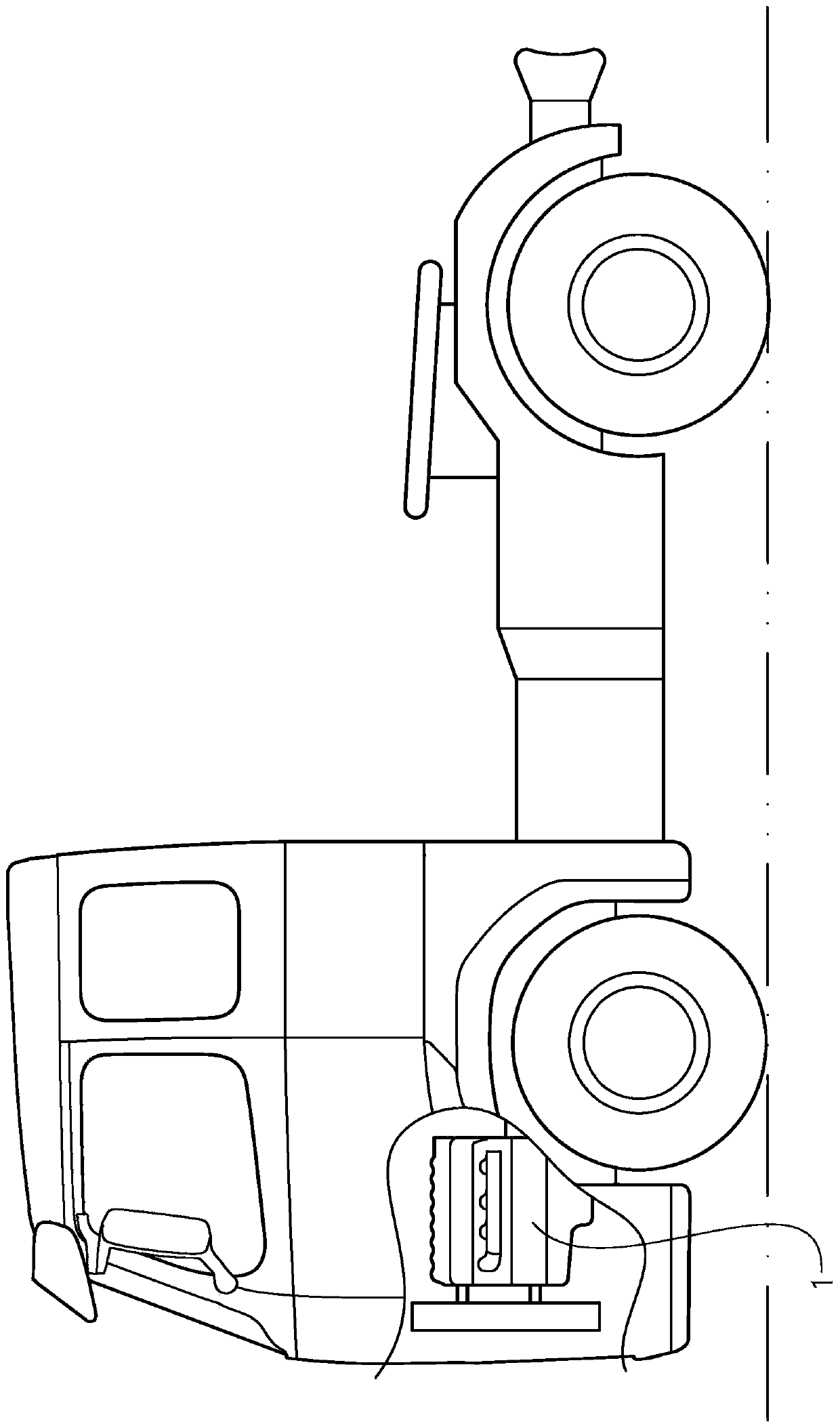
[0036] figure 1 A vehicle in the form of a truck or tractor for a semi-trailer is shown. It should be noted that the vehicle could be of various alternative types, for example it could be a car or a bus. The vehicle comprises a four-stroke internal combustion engine 1 . It should be noted that the invention is equally applicable to various engine types, such as two-stroke engines, engines adapted to the six-stroke cycle, camless engines, and the like.

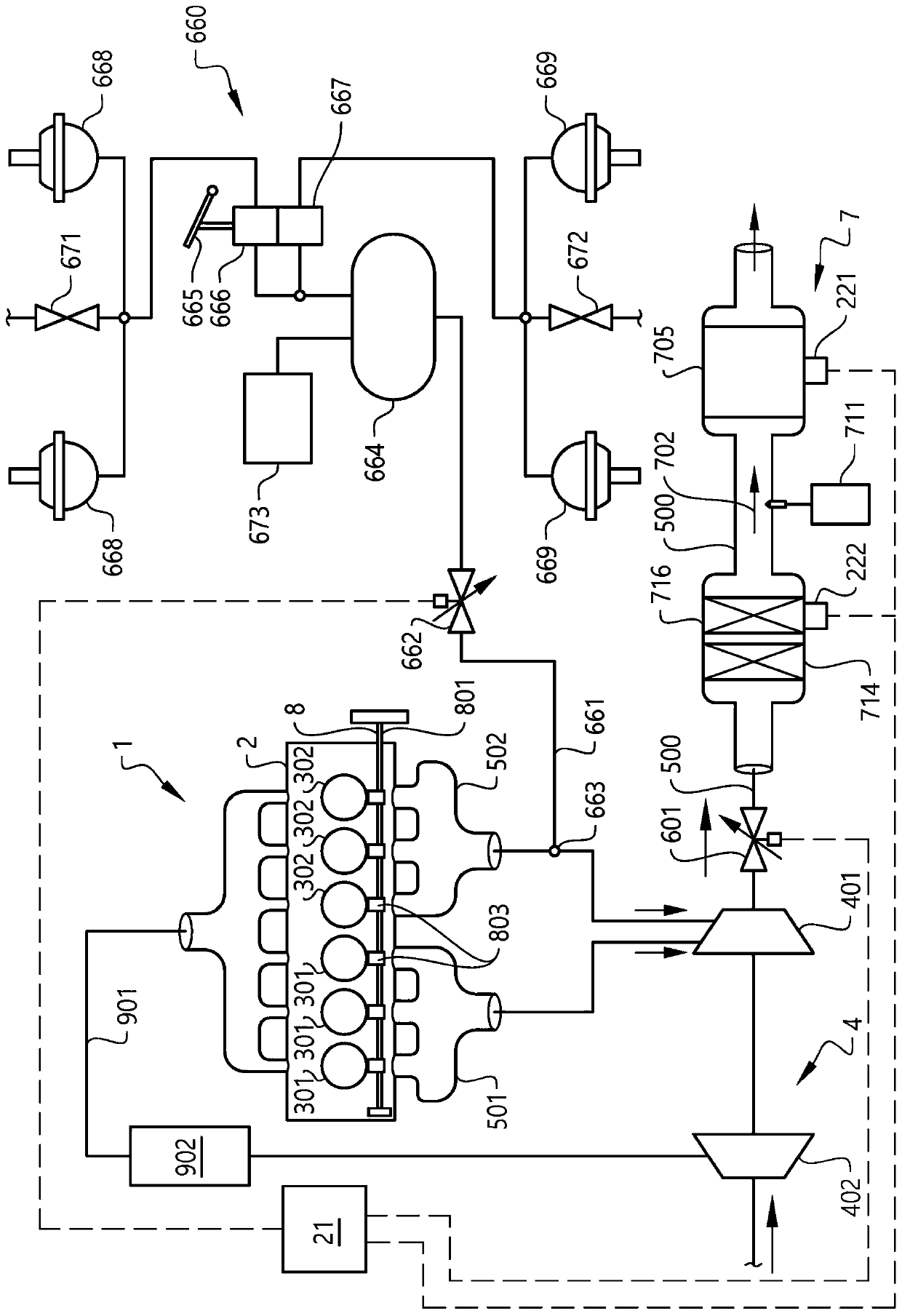
[0037] figure 2 The operating system of the vehicle including the engine 1 is shown. In this example, the engine comprises six cylinders 301 , 302 arranged in a row. Each cylinder 301, 302 includes a piston connected to a rotatable crankshaft (not shown). The engine 1 is oriented in this vehicle such that a bank of cylinders is parallel to the straight-line direction of travel of the vehicle. It should be noted, however, that in alternative embodiments, the orientation of the engine may have another orientation in the ve...


PUM


Abstract

The invention provides an operation system for a vehicle, comprising an internal combustion engine (1) comprising a cylinder (301, 302), and an exhaust guide (500, 501, 502) being arranged to guide agas flow from the cylinder (301, 302) to the atmosphere, wherein the vehicle operation system further comprises a pneumatic system (660), and an air conduit (661) connecting the pneumatic system (660)with the exhaust guide (500, 501, 502) for allowing a flow of compressed air from the pneumatic system into the exhaust guide (500, 501, 502).

Description

technical field [0001] The invention relates to an operating system for a vehicle comprising an internal combustion engine, a method of controlling the operating system of a vehicle, a computer program, a computer readable medium, a control unit and a vehicle. [0002] The invention can be applied in heavy vehicles such as trucks and buses. Although the invention will be described in relation to a heavy vehicle, the invention is not limited to this particular vehicle, but may also be used in other vehicles, such as passenger cars. Background technique [0003] It may be desirable to provide strong engine braking, especially in heavy vehicles, such as on long, heavily loaded downhill roads. The problem is that the engine braking process can raise the temperature of exhaust aftertreatment devices such as filters and catalysts to levels that damage them by converting braking torque into heat via air compression in the engine. As a result, engine braking power may have to be c...

Claims


Application Information

Patent Timeline
Patent Type & Authority Applications(China)
IPC IPC(8): F01N3/22F01N3/20F01N3/05
CPCF01N3/05F01N3/2006F01N3/2046F01N3/22F01N2270/02B60T17/02F02D9/06F02D13/04B60T17/22F02D41/12F02D2200/0802F02D2041/0265F02D41/0235Y02A50/20Y02T10/12
Inventor 延斯·佩德森安德斯·莫林
Owner VOLVO LASTVAGNAR AB
Why Eureka
Try Eureka