Wire rod laser cutting machine and laser cutting method thereof

A cutting machine and laser technology, applied in welding/cutting auxiliary equipment, auxiliary devices, laser welding equipment, etc., can solve the development trend of high input cost, increase manufacturing cost, large space for placement, etc., to meet the rhythm of the process flow Demand, reduce power consumption, small size effect

Pending Publication Date: 2019-11-19
DONGGUAN SANXIN PRECISION MACHINERY
View PDF0 Cites 0 Cited by
  • Summary
  • Abstract
  • Description
  • Claims
  • Application Information

AI Technical Summary

Problems solved by technology

[0003] However, if the double laser head structure is adopted, the double laser head will increase the manufacturing cost, and the operation will increase the power at the same time. Therefore, it is necessary to use high voltage and high power supporting products to ensure its reliable operation.
It can be seen that the overall structure of the equipment is large, the space that needs to be placed is large, and the investment cost is high, which does not conform to the current development trend.

Method used


Image

  • Wire rod laser cutting machine and laser cutting method thereof
  • Wire rod laser cutting machine and laser cutting method thereof
  • Wire rod laser cutting machine and laser cutting method thereof

Examples


Embodiment Construction

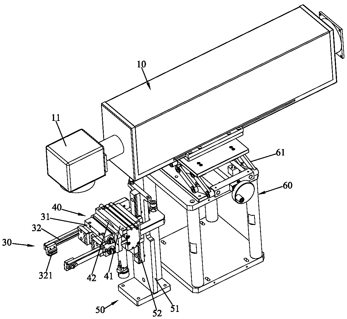
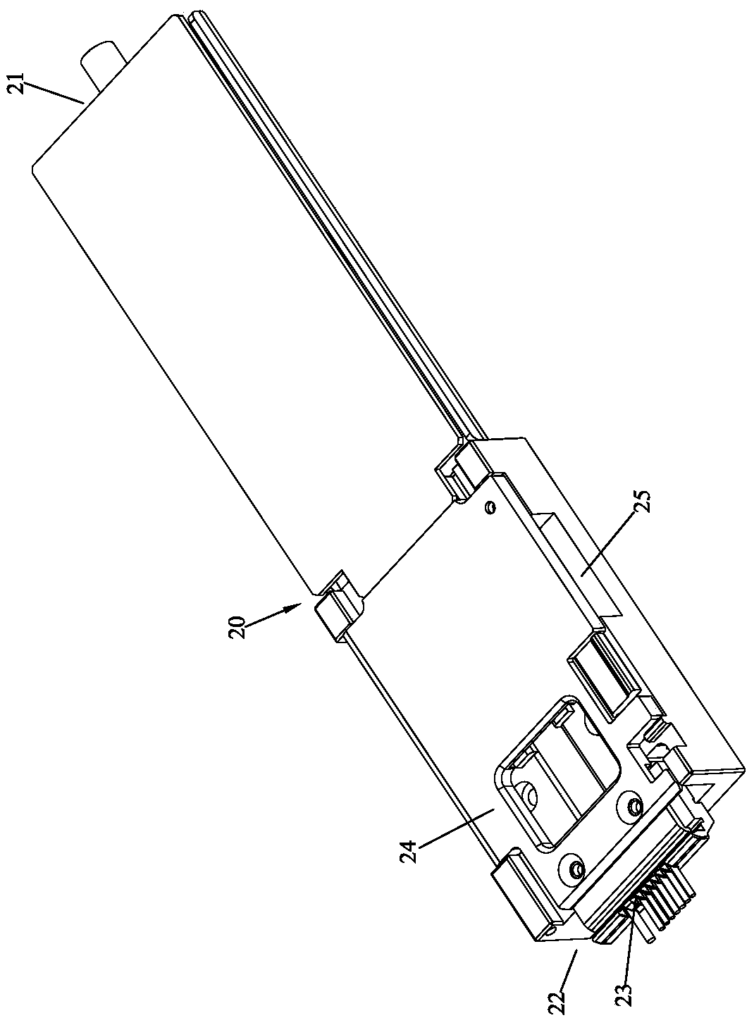
[0048] Please refer to Figure 1 to Figure 3 As shown, it shows the specific structure of the preferred embodiment of the present invention, which is a wire laser cutting machine and its laser cutting method, including a laser cutting device 10 for laser cutting wire and a clamp for clamping the wire Wire fixture 20.

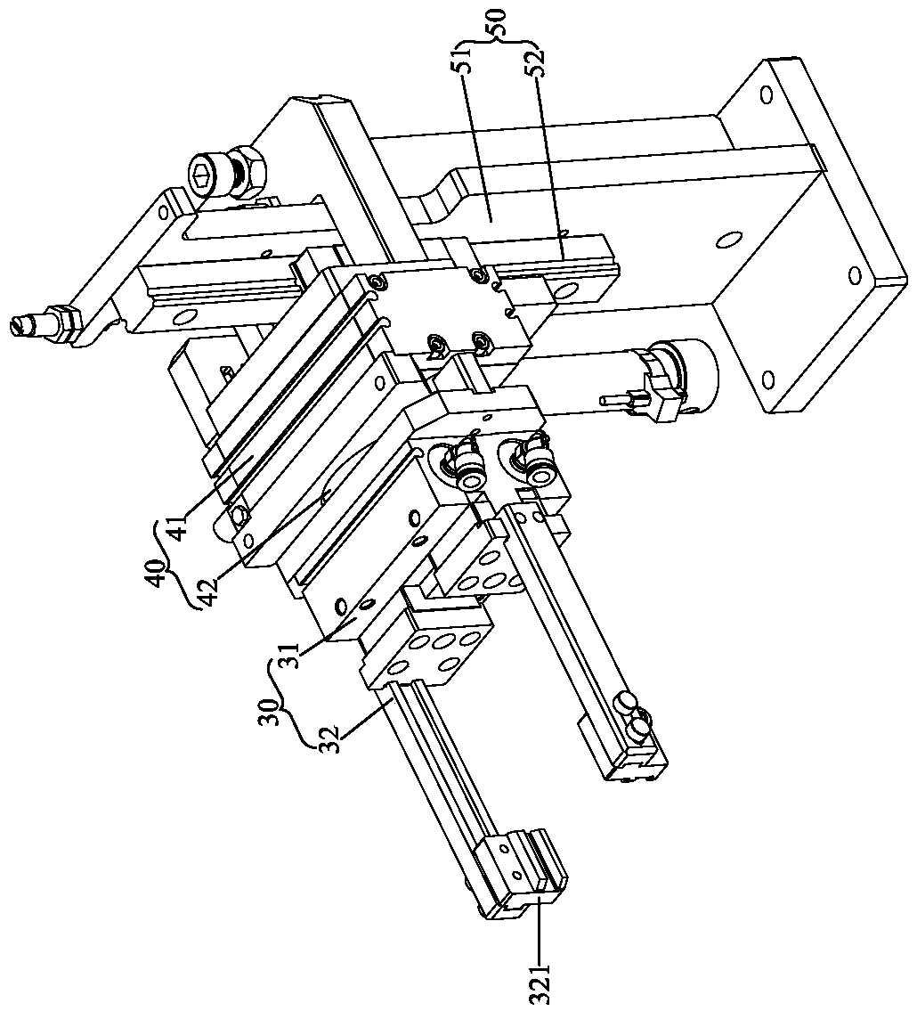
[0049] The wire laser cutting machine also includes a clamping mechanism 30, a turning mechanism 40 and a displacement mechanism 50, the clamping mechanism 30 is fixed on the turning mechanism 40, and the turning mechanism 40 is movably arranged on the displacement mechanism 50, The clamping fixture 20 can be selectively fixed on the clamping mechanism 30; the laser cutting device 10 has a laser head 11, and the displacement mechanism 50 can selectively move the clamping mechanism 30 to approach or move away from the laser head 11 .

[0050] In this embodiment, the displacement mechanism 50 includes a fixed plate 51 and a vertical displacement guide bar 52 arr...


PUM


Abstract

The invention discloses a wire rod laser cutting machine and a laser cutting method thereof. The wire rod laser cutting machine comprises a laser cutting device, a wire clamping jig, a clamping mechanism, a turnover mechanism and a displacement mechanism. The clamping mechanism is fixedly arranged on the turnover mechanism. The turnover mechanism is movably arranged on the displacement mechanism.The wire clamping jig is fixed to the clamping mechanism in a selectable manner. The laser cutting device comprises a laser head. The displacement mechanism selectively moves the clamping mechanism toget close to or away from the laser head. By arranging the laser head, turnover of a wire rod can be achieved through the clamping mechanism, the turnover mechanism and the displacement mechanism, and in this way, the laser cutting operation of the front face and the back face of the wire rod can be completed through one laser head, the structure of the laser cutting device is simplified and optimized, the manufacture cost of the device can be reduced, and the size of the whole cutting machine can be smaller. In addition, by omitting a laser function part, the electronic control part of the whole cutting machine can be simpler, and the operation stability and reliability are both substantially improved.

Description

technical field [0001] The invention relates to the technology in the field of wire laser cutting, in particular to a wire laser cutting machine and a laser cutting method thereof. Background technique [0002] With the advancement of science and technology, some electronic industries at this stage, such as integrated circuit boards, often need to be connected with upper cables. However, when soldering the cable, sometimes the aluminum foil or insulating layer on the outer layer of the cable must be removed. The traditional laser cutting machine for cutting the aluminum foil or insulating layer on the outer layer of the wire generally adopts a double laser head structure, which is set up as a mirror image up and down. Laser cutting operations are performed on both sides. [0003] However, the dual laser head structure will increase the manufacturing cost and the power will be increased at the same time. Therefore, it is necessary to use high-voltage and high-power supporti...

Claims


Application Information

Patent Timeline
Patent Type & Authority Applications(China)
IPC IPC(8): B23K26/38B23K26/70B23K37/047B23K37/04
CPCB23K26/38B23K26/702B23K37/0443B23K37/047B23K2101/32
Inventor 姚天金
Owner DONGGUAN SANXIN PRECISION MACHINERY
Why Eureka
Try Eureka