Airship structure design method based on air bag diaphragm and inflatable ring framework

A technology of structural design and design method, which is applied in the direction of airbag layout, aircraft parts, ground equipment, etc., can solve the problems that the deformation of the main bag body cannot be effectively controlled, and the operation mechanism is not considered, so as to achieve obvious practical significance and improve efficiency Effect

Pending Publication Date: 2019-11-19
HARBIN INST OF TECH
View PDF8 Cites 0 Cited by
  • Summary
  • Abstract
  • Description
  • Claims
  • Application Information

AI Technical Summary

Problems solved by technology

At present, there is no inflatable ring inside the main capsule of the airship, and the operation mechanism when several airbags work together is not considered, so the parts with large deformation of the main capsule cannot be effectively controlled

Method used


Image

  • Airship structure design method based on air bag diaphragm and inflatable ring framework
  • Airship structure design method based on air bag diaphragm and inflatable ring framework
  • Airship structure design method based on air bag diaphragm and inflatable ring framework

Examples


specific Embodiment approach 1

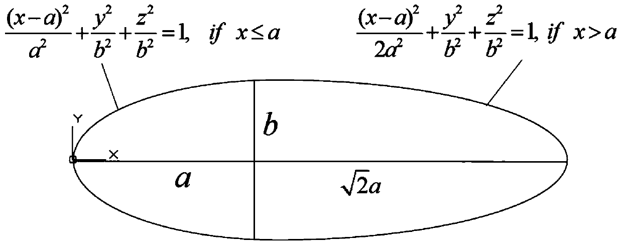
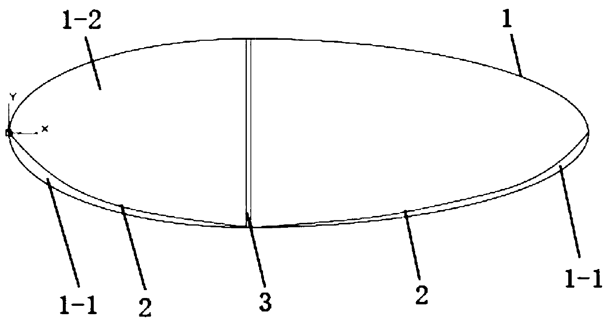
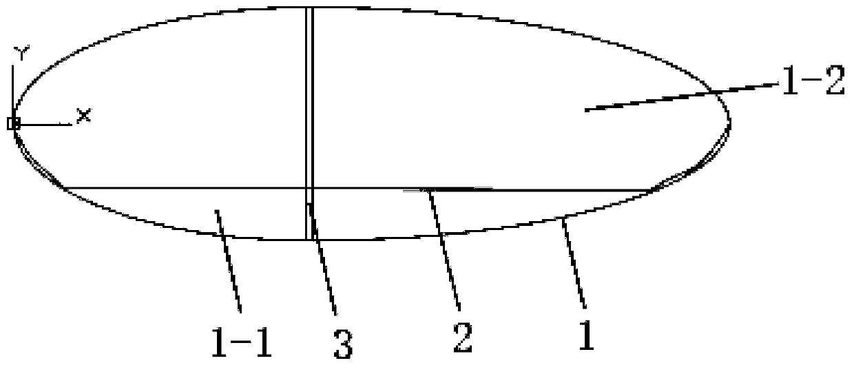
[0020] Specific implementation mode one: as Figure 1 to Figure 10 As shown, the present invention discloses a method for designing an airship structure based on an airbag diaphragm and an inflatable ring skeleton. The design method includes:

[0021] The configuration of the main capsule 1 of the airship adopts the design of double ellipse generatrix turning into a body. A diaphragm 2 is arranged inside the main capsule 1. The diaphragm 2 can be freely expanded and the edge of the diaphragm 2 is sealed and fixedly connected with the inner wall of the main capsule 1. The diaphragm 2 and the part surrounded by the lower diaphragm 2 of the main capsule body 1 forms an air bag 1-1, and the interior of the main bag body 1 is located above the diaphragm 2 as a helium gas existence area 1-2, and the air bag 1-1 and the helium gas existence area 1-2 Alternate inflation and deflation to change the pressure and volume, control the ascent and descent of the airship, and arrange a plural...

specific Embodiment approach 2

[0022] Specific implementation mode two: as Figure 8 As shown, this embodiment is a further description of Embodiment 1. The inflatable ring 3 is made of vectran fabric material, and the connecting cable 3-1 is made of Kevlar.

specific Embodiment approach 3

[0023] Specific implementation mode three: as Figure 5 As shown, this embodiment is a further description of Embodiment 1. The diaphragm 2 uses UHMWPE fiber 50D fabric as the load-bearing layer, and the polyenol functional film as the gas barrier film. The material surface of the load-bearing layer The density is 0.97g / cm 3 , The fiber specific strength is 3196kg m / kg, and the material surface density of the gas barrier film is 15g / cm 3 , helium permeability rate 0.18L / m 2 .24h. atm.


PUM


Abstract

The invention discloses an airship structure design method based on an air bag diaphragm and an inflatable ring framework, and relates to the airship structure design method. The method is characterized in that a main bag body configuration of an airship adopts a double-elliptical-bus rotary body design; the diaphragm is arranged inside a main bag body, the diaphragm can be freely expanded, and the edge of the diaphragm is fixedly connected with the inner wall of the main bag body in a sealed mode; the diaphragm and a part, surrounded by the diaphragm, at the lower part of the main bag body form an air bag; the area, located above the diaphragm, inside the main bag body is a helium existing area; a plurality of inflatable rings are arranged inside the main bag body at intervals, the inflatable rings are limited and shaped through four connecting cables, and the inflatable rings partition the whole air bag into a plurality of air bag spaces; and the head end and the tail end of the mainbag body play a role in the axial auxiliary supporting through a carbon fiber framework. According to the airship structure design method based on the air bag diaphragm and the inflatable ring framework, the inflatable rings are arranged inside the main bag body of the airship so that the deformation and stress of a part with large load bearing can be effectively controlled; the inflatable ringspartition the air bag into the plurality of air bag spaces to effect synergistically; and the inflation and the deflation of different air bag spaces is conductive to changing the gravity center of the airship to control the longitudinal movement.

Description

technical field [0001] The invention relates to an airship structure design method, in particular to an airship structure design method based on an air bag diaphragm and an inflatable ring skeleton. Background technique [0002] Stratospheric space is 20-100km above the surface, located above the troposphere and below the ionosphere. The weather and climate are stable and there is almost no electromagnetic interference. Its unique environmental advantages and military and civilian application value have become the focus of attention of countries all over the world. Stratospheric airship is a representative of long-term continuous flying aircraft in stratosphere space. It has broad application prospects and development potential in communication relay, navigation and positioning, meteorological observation, space exploration and other fields. Many countries such as the United States, Japan, Britain, Russia, etc. A large amount of money was invested in research and development...

Claims


Application Information

Patent Timeline
IPC IPC(8): B64B1/58B64B1/60B64F5/00
CPCB64B1/58B64B1/60B64F5/00
Inventor 林国昌王长国谭惠丰张季马瑞强马腾高伟楠
Owner HARBIN INST OF TECH
Why Eureka
Try Eureka