Novel vacuum induction melting furnace

A technology of vacuum induction melting and vacuum heating furnace, which is applied in the direction of furnaces, crucible furnaces, furnace components, etc. It can solve the problems of unreasonable design of induction heating coil structure, equipment can not work for a long time, and the heating time of the device is long, so as to improve the melting efficiency. The effect of maintaining vacuum and reducing the energy consumption of equipment

Inactive Publication Date: 2019-11-19
JIANGXI YG MAGNET CO LTD
View PDF1 Cites 1 Cited by
  • Summary
  • Abstract
  • Description
  • Claims
  • Application Information

AI Technical Summary

Problems solved by technology

[0005] In order to solve the above technical problems, the present invention provides a novel vacuum induction melting furnace. The existing vacuum high-frequency induction melting furnace used in the production of NdFeB magnets has high unit energy consumption, complex overall structure, long heating time of the device, and The efficiency is low, the structure design of the induction heating coil is unreasonable, and the equipment cannot work for a long time

Method used


Image

  • Novel vacuum induction melting furnace
  • Novel vacuum induction melting furnace
  • Novel vacuum induction melting furnace

Examples


Embodiment

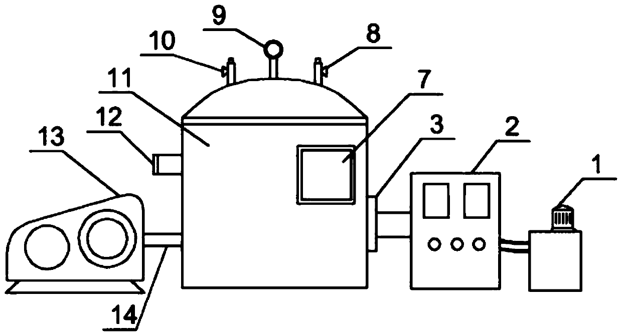
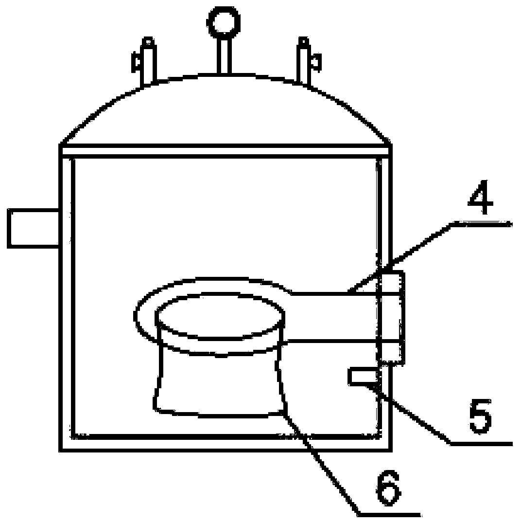
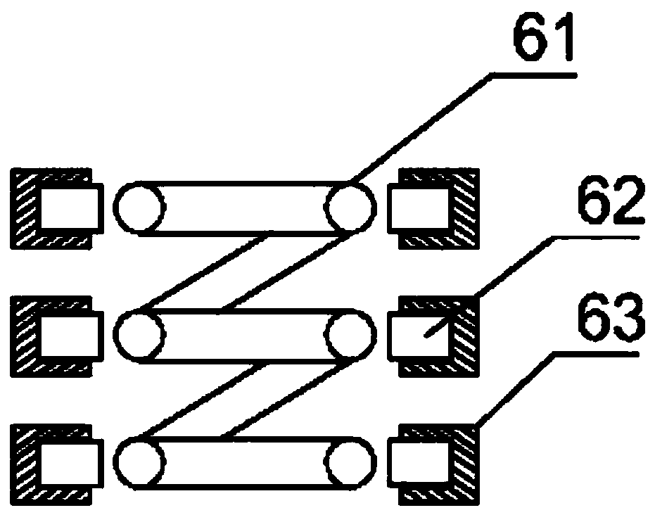
[0024] as attached figure 1 to attach image 3 shown

[0025] The present invention provides a novel vacuum induction melting furnace, comprising a cooling system 1, a high-frequency induction machine 2, an insulating partition 3, a high-frequency induction heating coil 4, a temperature detector 5, a crucible 6, a temperature display screen 7, and an air inlet valve 8. Vacuum gauge 9, intake valve 10, vacuum heating furnace 11, observation window 12, vacuum pump 13 and vacuum bellows 14, the cooling system 1 is connected with the high-frequency induction machine 2 through a cooling water pipe; The plate 3 is installed on the side of the vacuum heating furnace 11; the high-frequency induction heating coil 4 passes through the insulating partition 3 and enters the vacuum heating furnace 11; the temperature detector 5 is arranged in the vacuum heating furnace 11; The crucible 6 is placed in the high-frequency induction heating coil 4; the temperature display screen 7 is arrange...


PUM


Abstract

The invention provides a novel vacuum induction melting furnace. The novel vacuum induction melting furnace comprises a cooling system, a high frequency induction machine, an insulating partition plate, a high frequency induction heating coil, a temperature detector, a crucible, a temperature display screen, an air inlet valve, a vacuum gauge, an air inlet valve, a vacuum heating furnace, an observation window, a vacuum pump and a vacuum bellows. The cooling system is connected to the high frequency induction machine through a cooling water pipe; the insulating partition plate is installed onthe side part of the vacuum heating furnace; the high frequency induction heating coil penetrates through the insulating partition plate and enters into the vacuum heating furnace; and the temperaturedetector is disposed in the vacuum heating furnace. The high frequency induction heating coil, the temperature detector and the cooling system are arranged, the novel vacuum induction melting furnacehas reasonable structure and low unit energy consumption, effectively improve the heating efficiency of a NdFeB magnet raw material, facilitate the control of the heating temperature, effectively protect the heating device, and facilitate the market promotion and application.

Description

technical field [0001] The invention belongs to the technical field of neodymium-iron-boron magnet production, and in particular relates to a novel vacuum induction melting furnace. Background technique [0002] At present, the production of NdFeB magnets is mainly carried out by electromagnetic induction heating. Electromagnetic induction heating uses the thermal effect of current to heat the workpiece according to the law of electromagnetic induction. The 50Hz power frequency alternating current is converted into the required high frequency alternating current through the induction heating power supply. The raw materials required for the production of NdFeB magnets are placed in the induction coil, and the high-frequency current generates an alternating magnetic field around the workpiece. At this time, an induced electromotive force will be generated on the surface of the metal raw material, and then an induced current will be generated. When the magnetic flux passing th...

Claims


Application Information

Patent Timeline
IPC IPC(8): F27B14/04F27B14/06F27B14/08F27B14/20F27D21/02F27D99/00
CPCF27B14/04F27B14/061F27B14/08F27B14/20F27B2014/045F27B2014/0825F27B2014/0837F27D21/02F27D99/0073
Inventor 杨红星朱明王寰宇宋久宝陆柄森朱奇斌陈伟黄慧庆刘贯伟熊武文付国宝蒋声云林丽群张秋铭
Owner JIANGXI YG MAGNET CO LTD
Why Eureka
Try Eureka